Hey,
A search didn’t really help so I guess I’ll just post our problem:
We have the 2-color servo tracking example, which works when it is just run from the front panel. So we dragged the icon for the 2-color tracking into our autonomous code, and it still does the tracking when that is just run.
However, once that is in the autonomous and we try to build+deploy the entire main drive project, the camera does not do its tracking and instead shoots straight up.
Anyone got any ideas as to what could be wrong?
~Mike
(off-topic): We also can’t get our battery wired right. We had a mentor that said that it needs to be wired into slot 8 but she “didn’t know which module”?? We’ve looked all through our documentation, which yielded no results. It seems the battery should just be wired into the big “PLUS” and “MINUS” where it is, but the DS says 0.00v.
One thing for sure, the battery doesn’t get wired to slot eight, that is for relays. The battery should be wired to the analog breakout in slot one as far as I remember.
As for the autonomous code running, you may want to set breakpoints in C, or open panels in LV to see if the camera stuff is getting called, what params are being passed, etc. Be sure to enable and set the mode to autonomous, and make sure it is on blocks or otherwise safe.
Other folks who are more familiar with the tracking example can undoubtedly provide more information but I’m not sure that simply dragging-and-dropping that icon will work. The Basic (and Advanced) Robot Main VIs already perform a lot of the communication and watchdog configuration. You MAY be “configuring everything twice” by doing what you did. You might need to dig into the example and copy/paste certain elements.
Regarding battery voltage, please check the component datasheets at http://www.usfirst.org/community/frc/content.aspx?id=10934. In particular, chapter 3.4 describes the Analog Breakout and how it can be configured to measure battery voltage. All you need to do is attach a jumper on the outer 2 pins to feed battery voltage into Analog Input 8. Rule R64 requires that you install such a jumper.
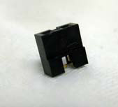
Just to be clear, I’ve attached a picture of the jumper(s) that should have been included in your kit-of-parts. These are NOT “jumpers” as in jumper cables used to re-charge a car battery.
In regards to the color tracking code, I copied just the parts for tracking and created my own subVI with inputs for the camera, image, etc. and outputs for the servo positions and tracking state. I also copied the servo updating loop directly into my vision proccesing vi.
The “jumper” connects two outside pins of the three pins on the edge of the Analog breakout board on top of the module in Slot 1 of the cRIO.
The “jumper” is a small black rectangular piece that fits over two pins.
The two positions of the jumper either connect the battery sensor (a resistor divider) to the eighth analog input, or in the second position allow you to use the regular Analog In 8 pins.
In Slot 2 is a second Analog Input, the jumper on that board should be in the other position, the inside two pins, allowing you to use the eighth input.