3636 Open Alliance 2022 Build Thread

Hello! We are Team 3636: Generals Robotics, from Portland, Oregon. We’re so excited to be a member of the Open Alliance for 2022.
We’ve never done an open build season before, but think this could be a good opportunity for us to help other teams like us getting back on track after the pandemic, and for us to get serious about our own goals and design process. We haven’t always been the most organized, but we want to share as much as we can, good or bad.
We are based out of a small storage room in our high school, measuring about 450 square feet. We also have a larger classroom that we can use as a temporary work space, but it is used for other classes throughout the day so we can’t store much in it.
We have approximately 30 active team members, and 3 primary mentors.

Tools & Equipment
3x Creality Ender-5 Pro: These take care of all our 3D printing needs. With a bit of tuning, we’ve managed to get very good accuracy and speed out of these printers, and we plan to upgrade them to print nylon filament in the near future.
2x Glowforge Plus: These are super useful for quick prototyping. Being able to create highly accurate plates in minutes drastically increases our efficiency in prototyping.
PDJ Pilot Pro 2642 CNC Router: Our router was assembled by students in spring of 2021. It’s taken us a while to set up and get it figured out, and we still have some work to do on it, but it has expanded our manufacturing capabilities quite a bit.
We also have other basic shop equipment such as a band saw, chop saw, belt sander. Our shop also has a small manual mill and lathe, but the team hasn’t used them and it’s unlikely we’ll need to in 2022.

Goals for the Season:

  • Complete the robot by the end of Week 4 of build season. In the past, many of our shortcomings have been caused by not enough time for driving practice and testing.
  • Train new members. Less than 25% of our team this year is returning team members. In order to keep the team strong past this season, we want to pass on as much knowledge as possible.
  • Strategic Robot Design. We know we can’t build a robot that can do everything, and we want to understand the game objectives that can make us competitive while staying within our limits.
  • Qualify for the PNW District Championship. To do this, we aim to be alliance captains or first picks at both of our district events.

Events
Team 3636 will be competing at:
PNW Wilsonville District (Week 2)
PNW Oregon State Fairgrounds District (Week 4)
Hopefully PNW District Champs (Week 6) and Worlds!

Google Photos Album
GitHub
CAD

9 Likes

Pre-Kickoff update: We’ve now consolidated all of our information into a Linktree page. This includes our team website, CAD, code, and all OA media for the season, which is now organized into separate Google Photos albums for each week of build season, as well as our Youtube channel. We also have photos of our build space posted as of now, and plan to upload much more media tomorrow at Kickoff!

1 Like

KICKOFF / Day 1-3 Summary

We had a lot of fun at Kickoff, and did a lot of brainstorming and strategic analysis. Overall, this game seems pretty balanced, with the high and low goals both offering benefits and drawbacks, and the high difficulty of the High and Traversal Rungs having a high payoff. Between chasing down bouncing Cargo and lining up for the climb, it’s clear that driver skill and coordination will be very important.

This is our overall priority list as of today. Our goal is to complete everything in the Needs category by the end of week 4 so we can focus on driver practice.

NEEDS

  1. Drive. We’ll be happily using the KOP drivetrain this year given the flat and open field.
  2. Climb on the Mid Rung. Doing so every match will give us 6 guaranteed points, as well as a decent shot at the Ranking Point if other teams have climb capabilities.
  3. Score Cargo in the Lower Hub. This will get us towards the Cargo RP in qualifying matches, and score a good amount of points if we have fast cycle times.
  4. Intake Cargo from the ground. With the Human Player station only starting with one game piece (which will most likely be thrown in auto), ground intakes are a must-have in our opinion.
  5. Hold 2 Cargo at once. We don’t see much reason not to.
  6. Build the robot using a 24x24” chassis. This will give us much more flexibility for climbing with other robots, which will increase our chances of getting the Hangar RP, and make us more valuable in alliance selection.
  7. Climb on the Low Rung. We also would like to climb on the Low Rung to enable 2 other robots to climb on the Mid Rung, earning the Hangar RP.

WANTS
8. Score Cargo in the Upper Hub. We’ll most likely only do this in playoff matches, when RP isn’t a concern and we need to maximize points.
9. Score 2 balls in auto. This would most likely mean building the robot to have an intake and shooter on opposite sides, so we could drive off the Tarmac, intake a cargo, drive back to the Hub and score both cargo.

LUXURIES
10. Climb on the High Rung. This is very challenging, and we don’t want to even attempt it until we have a solid plan for everything else.

In terms of actual robot design, we have ideas for most of our major mechanisms.

Climb: We ordered 2 Thrifty Telescoping Tube Kits on Saturday, which we’ll be using with MAX Planetary gearboxes for our climber. Right now we plan to use Falcon 500s at 20:1, and rely on the Falcon’s torque in Brake Mode to keep us lifted rather than any sort of mechanical brake. We’ve found that a single stage telescope with approximately 30” of travel can fit under the Low Rung, while still being able to reach the Mid Rung. We also plan to use double-sided hooks to make climbing convenient in any situation.

Shooter: Based on initial calculations in Julia’s trajectory calculator, we want to use a fixed-angle hooded shooter to score both the low and high goals from against the Fender. We plan to prototype the shooter extensively to test angles and speeds, and iterate the design accordingly. If we find that shooting the high and low goals with the same angle is impossible or just too inaccurate, we might pursue an adjustable shooter hood like many teams used in 2020.

Intake: Given our limited space, a full-width over-the-bumper intake with a V-hopper design seems a little excessive. However, given how ineffective our through-bumper intake was in 2020, we don’t want to try that again either. The solution we’ve tentatively settled on is something like this. We plan to use a 12” bumper gap (the maximum possible with a 24” wide frame) and intake the balls over the frame and into an indexer.

Electronics: Because of the over-the-frame intake mechanism, and how much of our frame the overall cargo mechanism will take up, we plan to use an inverted bellypan. This will give us much more space to put electronics, and provide a surface for the Cargo above the frame. Since we’re using only Falcon 500s this year (with maybe 1 or 2 NEO 550s), we won’t need to allocate space for many motor controllers.

Our plan is to have working prototypes of the intake and shooter by the end of the week, and get the climber assembled as soon as our MAX Planetaries and TTB Telescope kit arrive.

So far our CAD contains our climber, base drivetrain, and a prototype shooter design based on 4255’s prototype.

5 Likes

This is a simple trajectory calculator we created to figure out what launch angle will work best for a shooter at different distances. It also calculates the optimal launch velocity for a given angle and robot position (in a vacuum).

Shooter Trajectory Calculator

1 Like

WEEK 1 SUMMARY

Prototyping
We assembled our first prototype of a hooded flywheel shooter based on 4255’s design. We weren’t able to test it out much but from what we could tell we’ll need a fairly high angle to hit the “fender shot” into the Upper Hub.


We’ve also done some preliminary testing of wheels and surfaces against the Cargo. Overall, these are a very forgiving game piece in terms of grip and compression. They slide easily against polycarbonate, and can be squished to a reasonable amount. However, based on the possibility of inflation issues at competitions (similar to the original Cargo in 2019), we’ll try to aim for the higher end for compression.

Fabrication
We assembled our KOP Drivetrain, in the 24”x24” configuration with 6” HiGrip Wheels and Falcon 500 drive motors. We hope to get a basic electronics board done sometime next week and get a head start on driver practice.
We also manufactured the hooks for our climbers with the CNC router, and plan to get all of the components for that done by the end of next week so we can get it assembled and out of the way.

CAD
As of now, we have a mostly complete CAD model of the robot. It’s still missing some of the finer details (such as how to deploy and retract the intake) but we’ll hopefully be all done by the end of next week, and then tweak dimensions based on how our further prototypes go.

Here’s a quick overview of our mechanisms:
Intake: After initially being interested in a bumper gap intake, we eventually changed our minds and decided on a full-width over-bumper design with a hopper, similar to what many teams used in 2020. We plan to build the intake sides out of ¼” polycarbonate for impact resistance, and use a 4-bar mechanism to retract it vertically.

Indexer/Feeder: This is fairly simple, just some polyurethane flat belt on either side with 1” of compression on the ball. It’s designed to comfortably fit 2 cargo while still keeping our center of mass low and staying under the Low Rung. The front compliant wheels* help eliminate a dead zone between the intake and the indexer. The passive V-hopper design is just two pieces of bent polycarbonate, and relies on the intake and feeder wheels to push the balls in. We might also switch to a 1-sided design at some point, since the balls slip so easily against polycarbonate.
*(i know they’re floating in space, i’m working on it)

Shooter: Our shooter is currently a very basic design, just plates on either side with some axles and wheels, and powered by dual 1:1 Falcon 500s. Based on 7492’s prototyping, a lower “accelerator wheel” to get the ball up to speed seems interesting. Another somewhat similar idea is a separately driven wheel at the top of the indexer that would spin in reverse to keep the balls in place, then when we’re ready it would spin in the right direction to feed them up into the shooter.

Climber: No changes have been made since our first update. We’re keeping it simple for now and focusing on reliability with the Mid Rung, while leaving options open for improvement later.

Overall, I’m very happy with our progress this week. I think that the key to success this year is going to be driver practice, and getting a bot that we can hand off to the drive team as soon as possible is our main goal, even if it can’t accomplish everything in the game. Focusing on the Low Goal and Mid Rung and improving our consistency will score us reliable points and Ranking Points, and we can improve the robot as the season progresses.

9 Likes

Business & Media Update from our team’s COO, Zee Camp:

Hello,
During week One 3636’s business team has been focusing on two big pieces: 2022 Merchandise and a build season budget.

Every year we work to design a fun themed logo to place onto shirts and hoodies for our team to wear during competition season. A 3636 alumni, Aaron, had created us a beautiful perma logo to replace the silly school logo we had been using

it’s clean, witty, and represents us well. Being a airplane themed game my team began designing all sorts of initial logos, starting on paper and then working on either Adobe Illustrator or Procreate

Both of these were good initial options, but needed a lot of work. We ended up agreeing to make the front facing plane our 2022 logo, and the side facing plane will hopefully find itself somewhere on the back panel of the merch.

Our next version of the plane is as shows:

But in order for the design to read it had to be large on the shirt, something like this.

It was certainly an option but felt cluttered. This is when we recontacted our alumni for crucial design advice. He suggested we shrink the plane down so our brand is the focus vs the airplane. I agreed. We then got this!

And after placed on a t-shirt it looks like this:

We still have more work to do, and opted to continue this process into week 2. I am so incredibly proud of everything that was produced from my team. Even if we are behind schedule, the learning process has been crucial to everyone involved!

Budget:

For all 4 years I have been on this team, our budget has been something I have been working on. Initially, the biggest focus was on Sponsorships and funds, but now that we have the money, where should it go?

This is where I was lost, we always come up with an initial budget (looking a little like this)

But most of these numbers are no more than darts thrown on a board. Watching my team rapidly grow, I knew we had to sit down and come to some sort of real build season budget. I present to you, build season Budget V1

Now do I think this is completely accurate?? No, not at all. But I think it’s a good start to think about how much money we could be spending this season, especially if we do end up going to worlds (more on budgeting for the possibility of worlds another time). But it allows us to think about needs vs. wants, and keeps an open dialogue about our funds.

Zee Camp,

Signing off!

3 Likes

I really like this update and you all did an excellent job explaining your design choices.

4 Likes

WEEK 2: MID-WEEK UPDATE

Drive Practice
Our drive team has been practicing with our 2020 robot, driving around chairs and pushing around dollies to simulate basic gameplay. This was very basic, but hopefully we will have mechanisms to test with soon, as well as more game pieces to use on the field.

Field Elements
Our wonderful mentor Frank, with the help of several students, assembled our PVC version of the Hub. We hope to put a cardboard cone in the high goal for now, and for accurate bounce-out we can test on the real thing at Team 2471’s practice field.

Ball Feeder/Conveyor
We built a working prototype of a ball feeder system, mostly based on 3512’s results. 1.5” of compression ended up being the best, and to our surprise even worked on over-inflated balls.

These were our biggest takeaways:

  • The ball rolled the smoothest against polycarbonate.
  • With a one-sided design like ours, the ball wouldn’t get pulled up by the roller alone. However, simply adding a block of wood in the bottom corner made it work perfectly.
  • Polyurethane flat belt had more grip on the ball, making it easier to “grab” it into the conveyor as soon as it touched the belt. We did already have issues with the belt breaking, but that was most likely due to our very hasty belt welding.
  • Timing belts had more consistent compression and grip in the middle of the system, but had a harder time pulling the ball in initially.
  • We also had issues with the timing belt slipping off its pulley, even after tightening quite a bit. Using two belts right next to each other made them correct themselves whenever this occurred.
  • Adding compliant wheels to the bottom shaft helped a lot for the timing belts, and made them significantly better at pulling the ball in.

Based on this, our final design will use:

  • Between 1.25” and 1.5” of compression.
  • Two 15mm HTD timing belts in the center using 24t (roughly 1.5” diameter) pulleys.
  • Compliant wheels about 3” apart on the bottom shaft.
  • Bent polycarbonate in the corner to force the ball upwards.

Intake
We laser cut the plates for a prototype intake, but are still waiting on our TTB Squish Wheels to arrive before we can test it. Based on other teams’ results, and our own tests of the feeder, we’re inclined to believe that 1.5” of compression will be ideal for an intake as well.

Shooter
(Written by Peter, Co-Captain & Fabrication Lead)
We changed our shooter to be a 2-roller design to mitigate backspin, which we think will prevent bounce-out in the high goal. We tested several versions using only drills, but they weren’t fast enough to have much results.

We managed to install a CIM to power the bottom roller with a 1:1 ratio. Using a CIM on the bottom roller with a passive top roller worked better, but improvements still needed to be made. We received some new 4” Colson wheels and installed them onto the bottom roller, keeping the HiGrips on the top. This along with using a drill for the top roller helped immensely with power, and we could now easily score in the upper goal. We still had some backspin though due to the difference in speeds between the CIM and the drill.

Our next step is to install Falcons to both rollers and configure them. The Colson wheels seemed very effective so we plan to use them for the top, either the same size or smaller. We are also going to try to integrate the shooter and indexer prototypes so we can use them in series. We can find the most optimal spacing between them and prepare to mount the whole sub-system to our bot for drive practice. Once we do this we can fine-tune the angle and speed of the shooter.

We will also want to test the bounce out for different shooter prototypes and see how effective minimizing backspin helps that.

-Peter

CAD
Our overall design hasn’t changed much since last week, with the exception of the new dual-roller shooter. Mostly I’ve just been tuning up old sketches with precise compression numbers and belt C-Cs, and getting ready to start manufacturing some components like the bellypan. I did finally take care of those floating wheels, though!

We’re meeting again this Saturday and plan to test the intake with the TTB compliant wheels, test the shooter more with variable roller speeds to control backspin, try out smaller wheel sizes on the top roller, and potentially start integrating some of our prototypes into more complete subsystems.

4 Likes

WEEK 2
End of Week Mini-Update

We received our orders from TTB today, which contained our climber kits, compliant wheels for our intake, and some more bearings (you can never have too many!). We were able to finally test our intake, and we will also hopefully be assembling and testing our climb sometime next week.


(At least three of these are going on the robot.)

Intake Prototyping:
Our current intake is a 3-roller OTB design with about 1” of compression. We found that it was a good overall design, but did have some problems. The ball would almost always try to push the intake upwards, reducing grip and potentially creating a dead zone between the first roller and the bumper. When we held the intake down manually, it worked flawlessly.

This leads us to believe we might need some kind of additional force holding the intake down like springs or surgical tubing. However, based on our results with it held down we see no reason to change the compression, and we plan to start fabricating a (mostly) final version out of polycarbonate next week.

Intake Test Video

Indexer Prototyping:
We used our press brake to bend the ⅛ polycarbonate panels for the indexer and installed them to our 8020 prototype. Our main focus today was using the passive polycarbonate fins to center the balls in the main feeder. Unfortunately, our prototype was not completely accurate and had some 8020 getting in the way of the balls. The fins still mostly worked as intended, but we didn’t feel like the mecanum wheels added much to the design. We hope to come back to this mechanism next week to get more conclusive results.

Indexer Test Video

Other news:

  • We started making our bumpers today!
  • We finally resolved some long-standing issues with our CNC router that led to us having to replace the spindle and Variable Frequency Drive. We should have our full machining capabilities back for next week.
  • We updated the firmware on all of our Falcon 500s, which had caused some issues in earlier prototyping.
  • We finished fabricating a new shooter prototype, but didn’t have time to test it fully since all of the Falcons were in the hands of the programmers for most of the day.


Plans for Week 3:

  • Refine indexer and shooter prototypes to final versions
  • Fabricate final intake out of polycarbonate
  • Machine bellypan on the CNC router, as well as some additional parts for the climber
  • Assemble TTB climber mechanisms
  • Integrate all major prototypes into a “Proto-Bot” for drivers to practice with
  • Finalize CAD and begin manufacturing final parts for week 4!
2 Likes

WEEK 2
CAD Review

Last week I posted a deep dive into our CAD and design process, so here I go again with what’s changed throughout week 2.
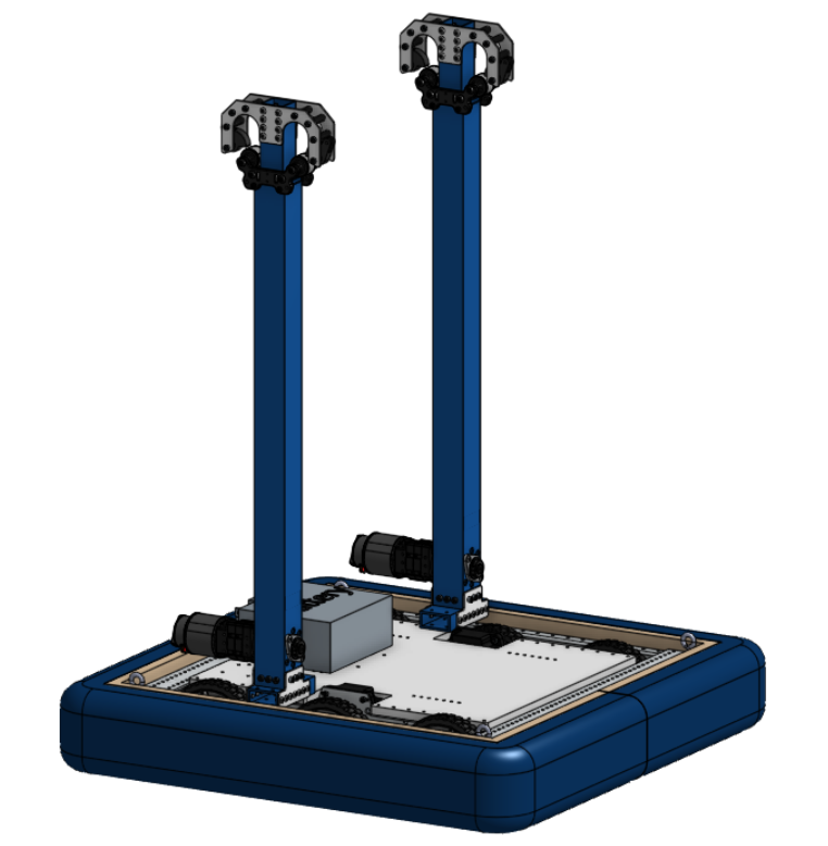
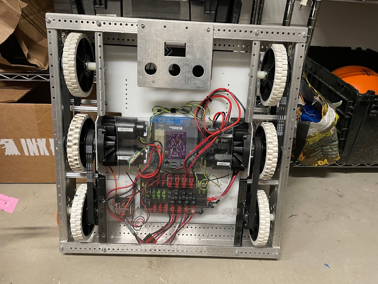
Electronics

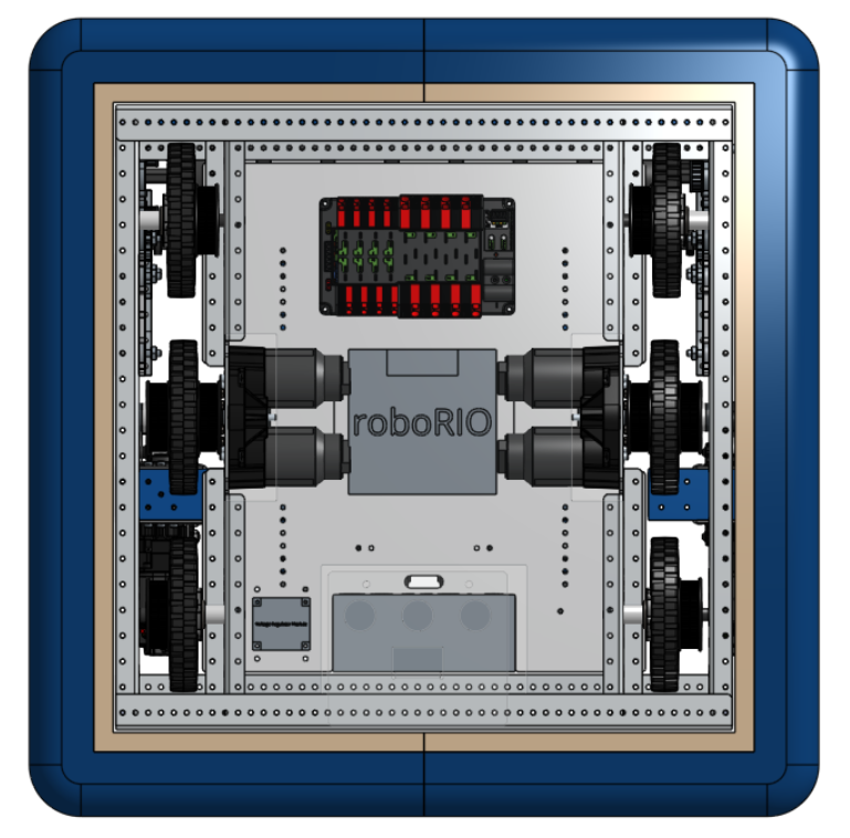
We decided to mount the battery vertically within the frame, rather than horizontally on top of the brainpan. This was to make it easier to hold in place during the match, as well as to shift weight downwards and towards the back. It also means changing up our electronics layout, which we’re still figuring out the best solution to. Right now our best options are either to put the PDP between the drive motors, which doesn’t give much clearance for wires, or to put the PDP on the other side of the robot from the battery, which would mean longer wire runs.


Neither of these are ideal.
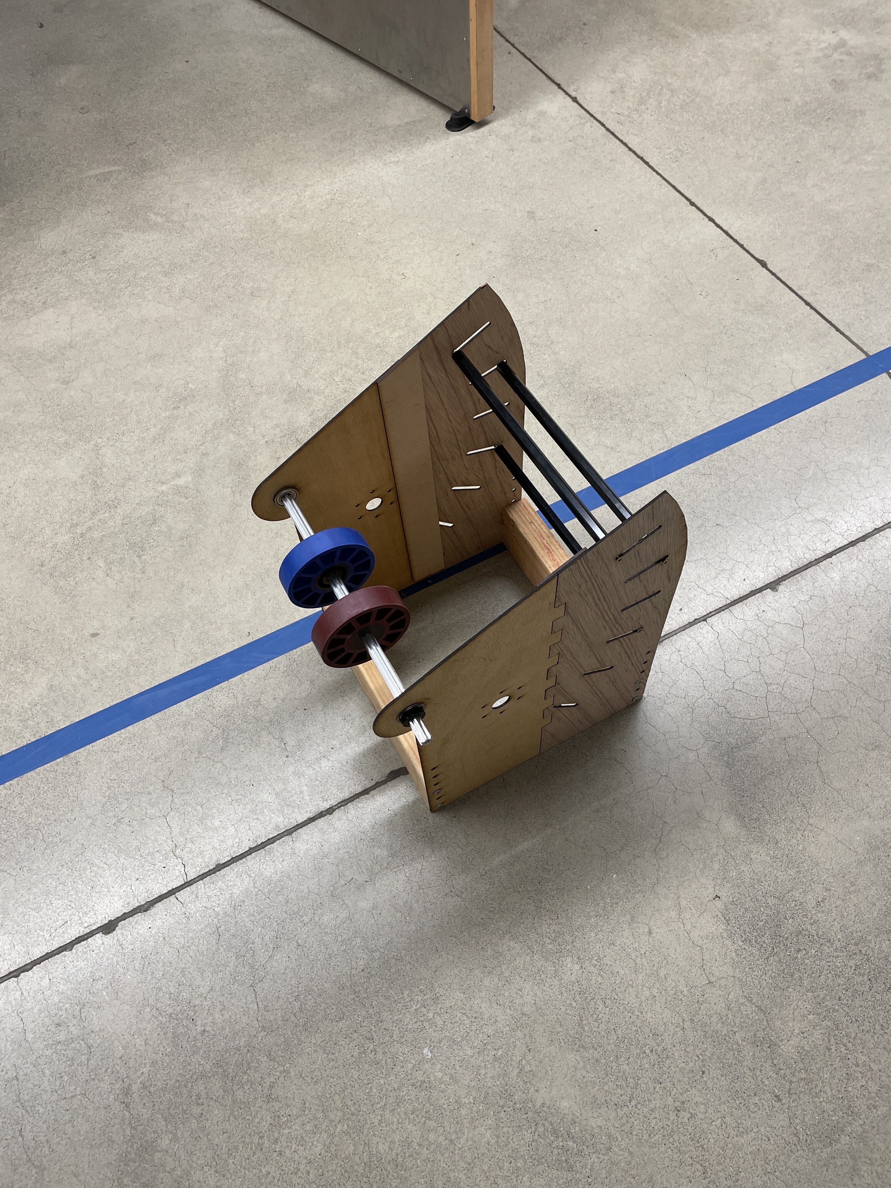
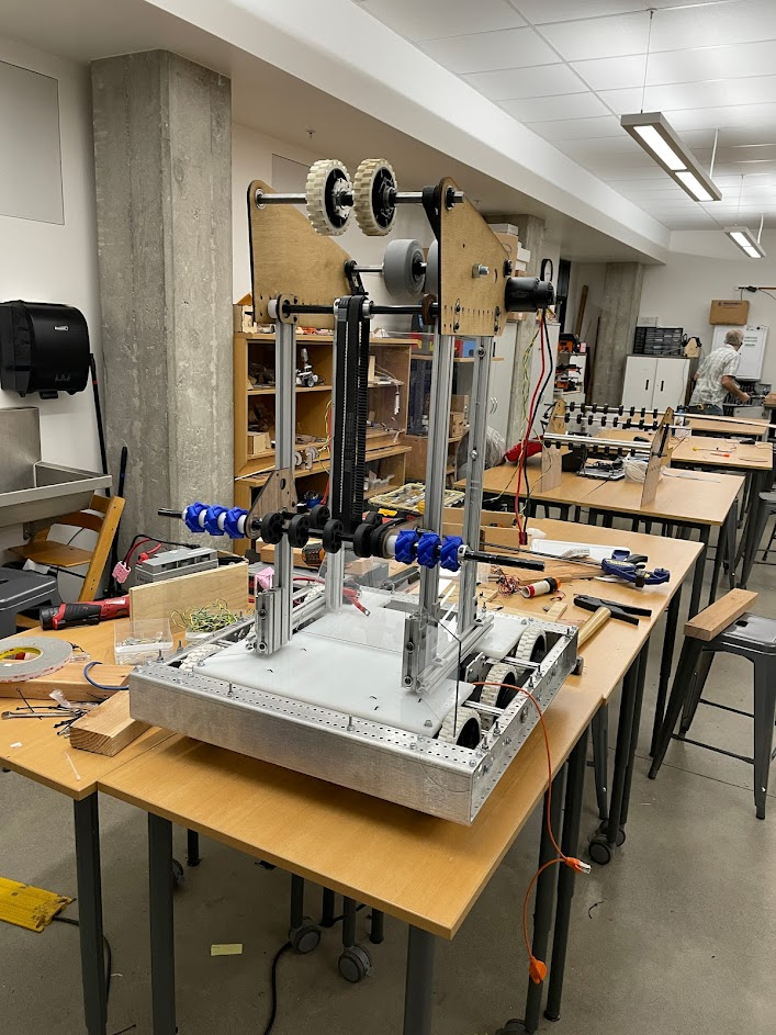
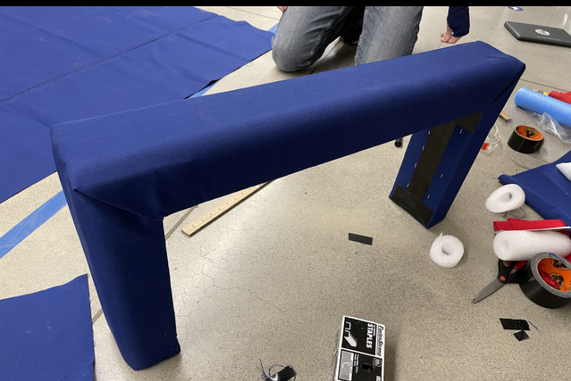
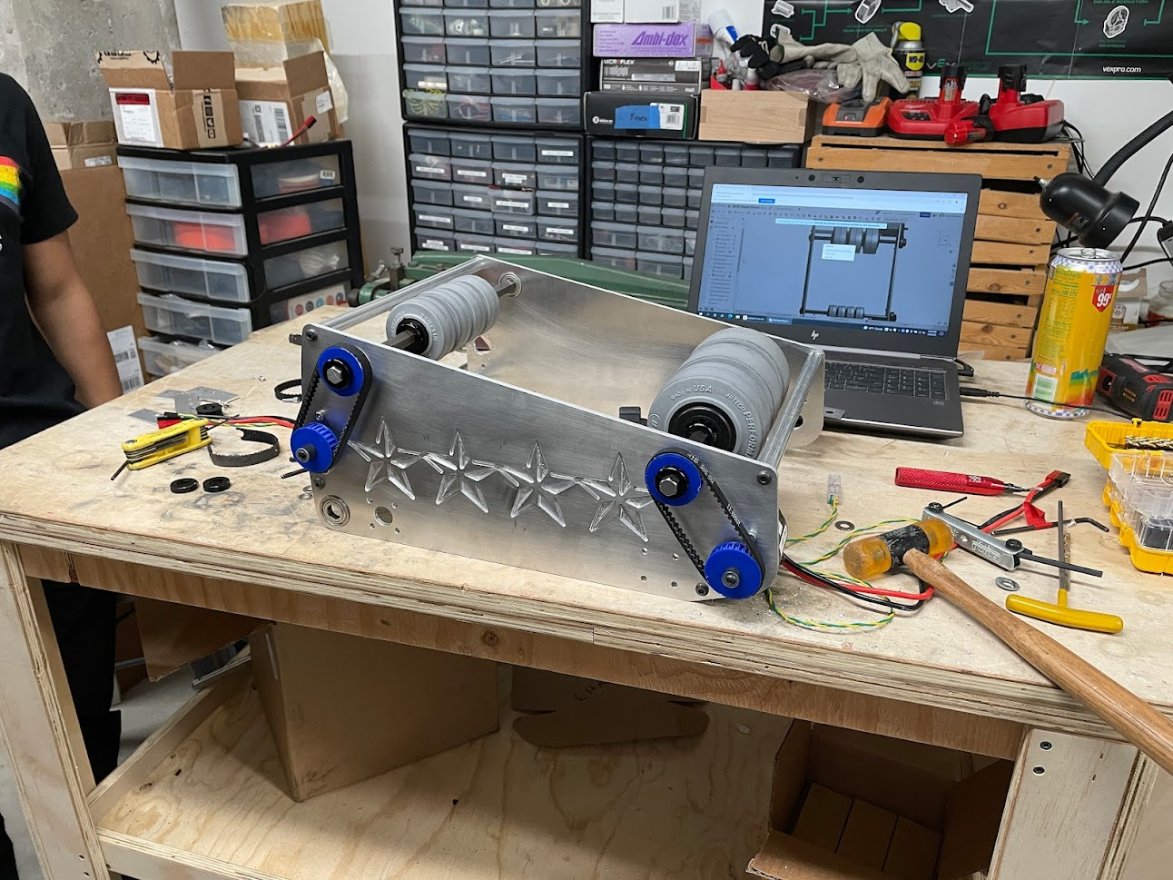
Climber

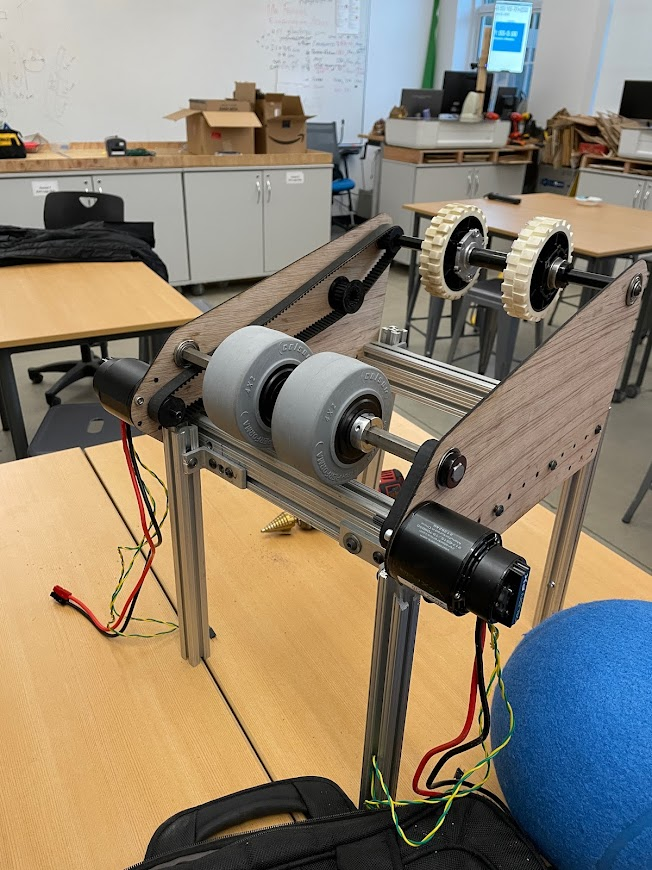
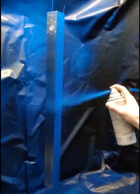
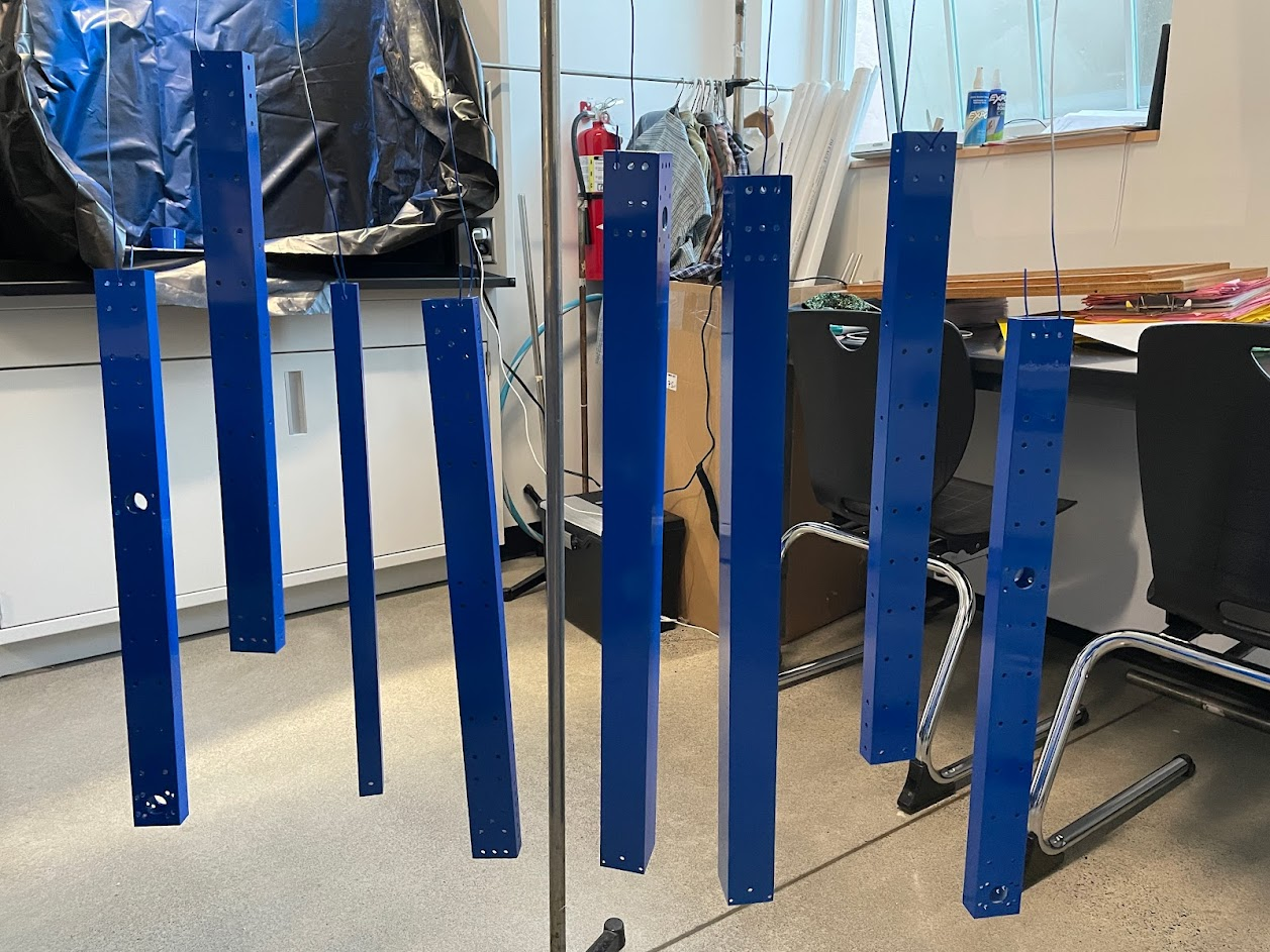
The climber has still barely changed since early week 1, but here’s some more explanation of the mounting system and overall design process:

The tubes are held to the drivetrain via a horizontal tube that goes across the drive rails and attaches to the brainpan and drivetrain. This is then attached to the outer tube of the climber using a WCP tube plug, as well as gussets on the sides. Originally, these tubes were one conjoined cross tube, but it ended up getting in the way of the main structure and was cut into two smaller pieces.


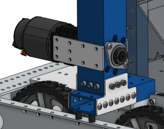
On the main tube itself, there are mounting holes for the MAX Planetary on one side, and clearance holes on the other side to access the mounting bolts. There are also holes to attach the 3/16” plate that supports the outer bearing. The MAX Planetary is then also supported by gussets on the sides (shoutout to REV for making it exactly 2” wide!).

An idea that we’re considering is the addition of some kind of bracing between the tubes, similar to the one sold by AndyMark. Since it won’t be too hard to implement down the line, we’ll stick with the current design for now and add it later if necessary.


Within the tube, we switched from our original idea of 3D printed spools to just using the shaft itself as a spool, with shaft collars to constrain the rope. Because of how much disassembly is required to access the spool, we decided that 3D printing just wasn’t worth the risk of failure. This also means we can use a much lower gear reduction on the motor, which frees up MP cartridges for use elsewhere (we currently have only 2 of each size).
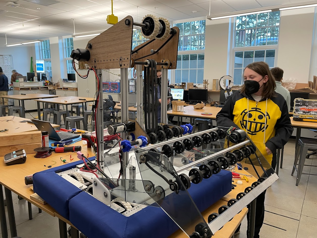
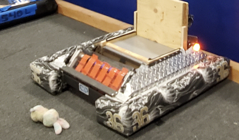
Intake

Barely anything has changed here. The mounting system is now a little less scuffed, with bearings on one side and a 1/4”-20 bolt going through the arms with a nut holding it in. I know bushings would be easier and cleaner, but we don’t have very many - and we do have a ton of these 3/8” ID x 7/8" OD bearings.

I’ve been thinking of ways to put the pivot points a little further apart for increased stability, but it doesn’t seem too big of an issue, and most mounting solutions on the KOP drivetrain are not ideal.
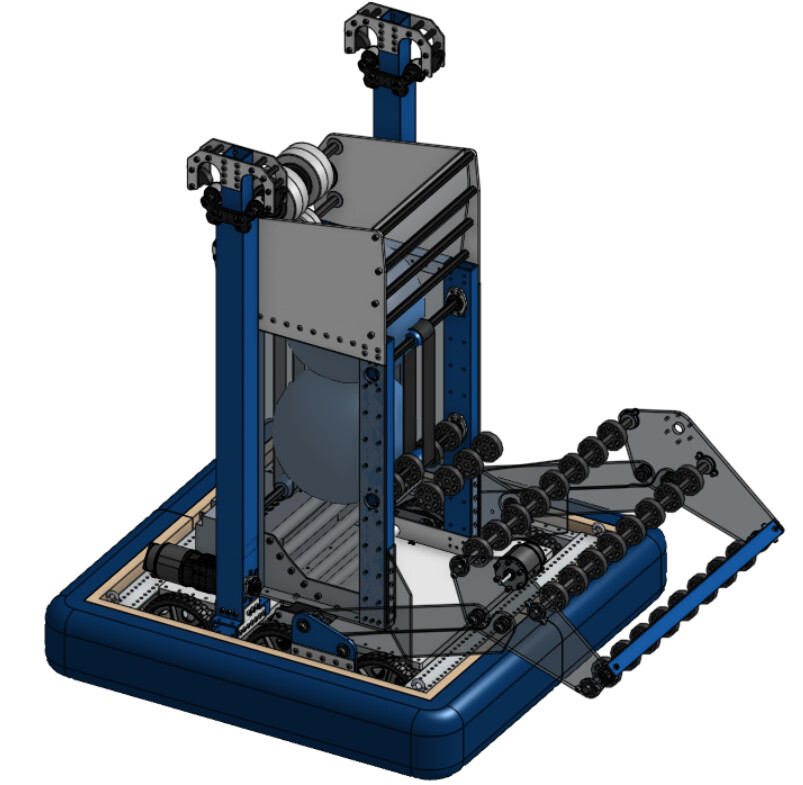
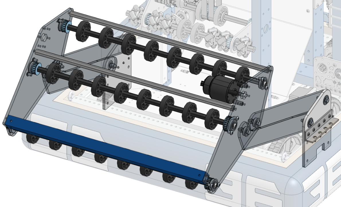
Indexer/Feeder

The feeder has been simplified quite a bit since the first iteration. It went from a double-sided conveyor with PVC rollers in the corner to now just a single set of belts and a sheet of polycarbonate. We switched from flat belts to timing belts for ease of manufacturing, and because the timing belts seemed to have more consistent grip on the ball based on our tests.

In the first iteration of the one-sided design, the corner was curved 1/16” polycarb, but then was changed to bent 1/8”. This is just because we have a lot more 1/8” than 1/16”, and our press brake is convenient to use.


The other addition is mecanum wheels on the outer shaft. The jury’s still out on how much these actually help center the balls, but they don’t seem to hurt, and we do have a lot of 3D printed ones from 2020.

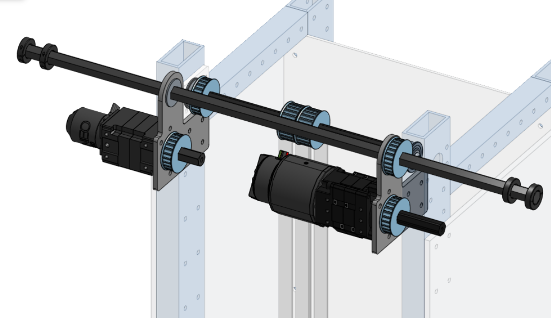
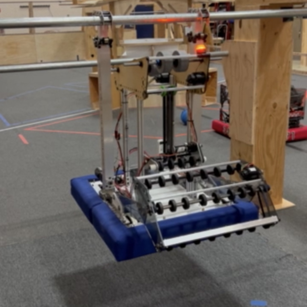
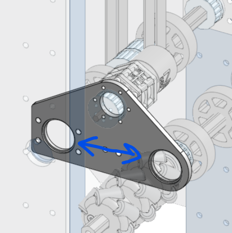
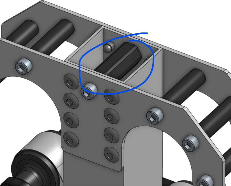
We also added this assembly at the top, which serves to both power the conveyor and deploy the intake via a winch.


The Falcon 500 goes to the winch shaft, while the NEO 550 goes to the belts. The plates are symmetrical, which means we can just machine two of the same.


This is how the intake winch works. It’s a little weird, but I think it could be effective.

Shooter

The shooter has gone through many iterations, the main change being from a traditional hooded design to a dual-roller design. We believe this will give us more effective control over the backspin on the ball, making it easier to avoid bouncing out of the high goal.

Our original prototype from earlier in the week used two sets of 4” HiGrip wheels, with the lower wheels eventually being switched to 4” Colsons. However, based on other team’s tests (and many designs from 2020/21) we think that having smaller wheels on the top will lead to more consistent shots. We plan to order several 2.5” Colsons early week 3, and hopefully have those soon enough to do some more tests before we fabricate the final version.

We also got rid of the “accelerator wheel” after tests showed that slower feeding worked just fine for making the fender shot.

The shooter is powered by two 1:1 Falcon 500s. When we switched to the dual roller design, we originally thought to power both rollers from both motors. However, we realized that having the speeds independently controllable could give us much more control over backspin, and so now each roller is powered by one motor. Since we want our shooter to be able to make both the high and low shots, ideally both from the Fender, being able to control spin could make that a lot easier to pull off.

Some Thoughts on Strategic Design

A major focus of my design philosophy is “raise the floor before you raise the ceiling”. In FRC, consistency is the key to success, no matter what level of competition you’re at. The best teams aren’t successful just because their robot’s ceiling is higher than yours or mine - they’re the best because their floor is higher than most teams’ ceiling. And at the district event level, more often than not, simple robots that can score consistently seed higher than flashy high-goal robots that can’t score reliable points and RP.

The phrase “build within your limits” has been said many times by many people much smarter than me. The problem, of course, is trying to balance between staying within limits and pushing them in order to be more competitive. This is especially true for teams like mine who can’t build a robot that can do everything, but can build a simple, effective robot really well if we put our minds to it.

What I’ve learned is that the key is to overreach smartly. Aim to push your limits, but always keep a strong, reliable concept within them to fall back on. This year, the Lower Hub and Mid Rung are something that every robot that makes eliminations, no matter how simple or how advanced, should be able to do. And so no matter how much we try to reach for the high goal or the traverse climb, our first priority has to remain on those two objectives. That’s our floor. And after that, the only way to go is up.

-Charlie Becker

10 Likes

WEEK 3
END OF WEEK SUMMARY

Week 3 went great for us. We stayed on track and completed almost all of our goals for the week, which is incredible given how aggressive some of our schedule was. We experienced plenty of setbacks, but I’m still feeling very confident that we can have a finished bot by the end of week 4.

We also went on FUN’s Open Alliance Show this Tuesday, where we talked about our goals for the season, as well as an overview of our CAD and prototypes.

Brainpan & Electronics
We machined the brainpan out of ½” HDPE on the CNC router. Compared to our struggles these past few months with machining metal, plastic is almost too easy… 80 IPM and 20k RPM cut through HDPE like butter.
We attached the brainpan to the bot and set up the electronics. This is our first time mounting upside down, and turning the bot over will take some getting used to, but we got everything wired together and ready to go. With that, we were ready to start integrating our prototypes.

Conveyor & Shooter Prototyping:
The conveyor prototype was mounted to the brainpan and adjusted slightly to fit with the intake. We weren’t able to do much shooter practice, but we were able to start playing around with different speeds on the top and bottom roller. We found that we were able to manipulate shot angle considerably by changing the speed of the top roller relative to the bottom. We hope to do more testing next week, as well as with 2.5” Colson wheels on the top roller, to find the ideal setup for both the high and low goals.

Intake:
We machined the intake plates out of ¼” polycarbonate, cut and tapped some shafts, and assembled the intake. Testing it out confirmed my suspicions that the geometry of the linkage would prevent balls from pushing the intake upwards as they went in. Overall, the intake works wonderfully, and we’ll most likely keep this version for the final bot.

Intake Linkage in action

And with that the Proto-Bot was done!* We took it out to team 2471’s practice field on Thursday night to test. We found a couple flaws, such as a small dead zone between the intake and conveyor, as well as the RoboRIO almost falling out of the robot (don’t trust VHB tape on upside-down electronics!). We ended up getting our testing cut short by one of the wood prototype pieces on the conveyor breaking. Overall, the intake and conveyor work well, and the shooter looks promising; after tuning the speeds a bit, we were able to get a couple balls in the high goal from the fender.

First intake & shooter tests at 2471’s field
More videos in our Google Photos Album (link is at the bottom)

*Except for one thing…

Climber:
When we ordered our TTB climbers on Kickoff, we didn’t think much about the box tube we needed for them. We have a local metal store that we go to for sheet, tube, and hex stock with good prices and no waiting for online orders to ship. It wasn’t until this week that we got around to going there to buy the box tube. And of course, they were out of the 2”x2” 1/16” wall box tube that we needed. We called around to other places, and apparently so was every other metal store in Portland.

Unfortunately this means the climber won’t be built until next week. One of our mentors managed to find some that should arrive over the weekend, and from there we can start fabrication. We didn’t bother machining any of the other remaining gussets since we were mostly focused on the intake, but those should be quick when we return to the shop on Tuesday.

Although the climber situation was frustrating, in the end it forced us to focus more on our other goals, which kept us well on schedule for the rest of the robot. I’m so proud of how far we’ve come so quickly, and I’m really excited to see how this robot turns out.

Goals for Week 4:

  • Machine remaining gussets and tubes for climber
  • Assemble climbers
  • Test shooter wheels, speeds, and angles to finalize design
  • Drive practice with Proto-Bot
  • Manufacture final parts (Conveyor box tubes, shooter plates)
  • Spray paint all final parts
  • Assemble the bot!!

Google Photos Album: Week 3
CAD

5 Likes

Don’t Forget the Bumpers!
Why and how your team should make their own
A brief summary of 4 years of bumper experience by Zee Camp

Hi Friends!

This is your friendly neighborhood COO and self proclaimed bumper god of Team 3636, Generals Robotics. This week we have started (and almost completed) our bumpers for the 2022 bot. However, I want to take a step back to explain our bumper journey

These were our 2018 bumpers, a janky take on reversible bumpers - but these are also the very things that got me hooked. My grandmother taught me how to sew at age 6, and I ran with it. (Currently I still sew quite regularly, and also have taken up other crafts such as crochet and embroidery.) I knew I could do better, but I also had no clue what I was doing.

This was my attempt at reversible bumpers circa February 2019. I was ambitious, and I still believe it was a good concept. Instead of sticking with Velcro, I used snaps to secure the flap. It… did not go well. The friction of the robot on carpet, as well as the small bumps and ramps on the 2019 field ripped out most of the bottom snaps right away, and they just looked, well, messy. I ended up just cutting my losses week 1 of comp season and making more bumpers

These looked better, but I still wasn’t happy.

Since no one on my team had much advice to offer, I started asking others. At every event we went to, I would go to each team and ask them how they made their bumpers. This caused me to make an unexpected discovery.

Over 70% of teams I asked told me that parents or mentors made their bumpers. Some of the teams with the nicest bumpers actually had professional seamstresses make them.

Now to be honest, bumpers are not as easy to make as everyone thinks. There are strict rules you must follow that can be quite finicky. However, I truly believe that having your students make the bumpers can improve every team.

I became determined to make the very best bumpers I can, and I’ve improved vastly. This is the progression of the bumpers I have made from 2019 to 2022.

Much better!

These are my best tips and tricks for bumper making:

  1. When possible, make two piece bumpers. It makes it a hundred times easier to attach and fit. I would only make one piece bumpers if it’s 100% necessary for the design, or if you’re attempting double sided bumpers. Which leads me to…
  2. Do not attempt double sided bumpers unless you truly know what you’re getting yourself into. I would only do it if you have practiced it in the off season. This requires pattern drafting and extreme precision. The most successful double sided bumpers I have ever seen was from 3663, they were designed by a seamstress and are truly works of art. For almost every other case, I would recommend just making two sets of bumpers.
  3. Measure, measure, measure… I cannot say this enough. Bumpers seem simple but there’s a lot of math that goes into them.
  4. Pool noodle precision. Pool noodles can be quite unwieldy -I suggest first taping the two pool noodles together, and then taping them to the bumper. I personally like the look of squared sharp corners (created by cutting each bumper at a 45 degree angle to achieve a sharp corner) but it truly is preference. Pro-tip: buy your pool noodles in the summer, I went through about 15 pool noodles total this season, and they’re much harder to source in the middle of January.
  5. Fabric Choice. My personal favorite bumper fabric is duck canvas; it’s cheap, durable, and sold at both Jo-Ann’s and Michaels. Outdoor/waterprooffabricsc are great but costly. I personally hate sail cloth but I think that’s just my bias. Don’t buy your fabric online unless you’re confident, it’s bitten me in the foot a couple of times. Depending on the width of the fabric one to one and a half yards should suffice (I always get 2 just to be safe but always have a lot left over.)
  6. Upholstering: all fabrics have at least a little bit of stretch. This can be mitigated by washing it before you use it; this will lead to the least amount of wrinkles in the bumpers. Cutting the fabric into strips about 14”wide tends to be just about perfect. I personally tape the fabric down before stapling it, which helps me keep the fabric in place, and map out how the fabric lays.
  7. Sew sew sew. Hand sewing the seams of the bumpers not only holds them together well, but also looks quite appealing.
  8. Numbers. I like to paint on the numbers on our bumpers, it’s fun and calming to me. However both embroidery and vinyl work super well too. You just have to then consider where the numbers are when upholstering, since both of those methods must be done before you attach the fabric to the pool noodles

Without further ado, here’s our bumpers (As of yet, these don’t have numbers or brackets)

Lastly, here’s my thoughts on why making bumpers is important.

Bumpers are some of the first things you notice when you look at a robot. They’re also the key feature to protecting our robots from harm. And who’s to say that skills such as sewing and upholstering are any less important than machining, programming or CAD? There is a huge huge industry in fabric and upholstery that is often forgotten. Bumpers are also a great way to involve people who wouldn’t ordinarily join a robotics team. For me, I mostly focus on the business side but making these bumpers helps me feel connected to the mechanical side as well. As both aesthetic and protective, bumpers work the left and right parts of your brain.

Anyways, that’s it. Thank you so much for a long read, I hope this will inspire you or your team to create the best bumpers yet!

Please reach out to me at [email protected] if you have any questions or want more bumper advice!

Zee Camp

18 Likes

WEEK 4
END OF WEEK SUMMARY

For the first time in our team’s twelve years in FRC, we completed a working robot during week 4 of build season.


So, how did we get there?
When we started this week on Tuesday, the robot was mostly complete, just needing some refinements to the shooter and the addition of the Mid Rung climbers.

On Tuesday, we machined the tubes and gussets for the climber, and began assembly on them. We also updated the prototype shooter, adding reinforced 3D printed pulleys with Vex inserts, and changing out the HiGrip wheels on the top for more 4” Colsons. By Wednesday, we had the climbers working while the drive team was practicing with the shooter. On Thursday, we spent the afternoon attaching the climbers and then headed up to Camas to practice at team 2471’s field. We tested the shooter and climber extensively, and got some valuable results.

On Saturday, we machined the last remaining box tubes and disassembled the robot to prepare for painting and final assembly. We spray painted all of the tubes, and on Monday of next week we’ll assemble the final painted robot.

Shooter
We tested the shooter with the 4” wheels on both sides at 2471’s shop, and after an hour or so of tuning speeds we were able to hit the low and high goals fairly reliably.

On Saturday, we also built a version of the shooter using 2.5” Colson wheels on the top roller, and we plan to test it next week. We’re sticking with the laser-cut wood plates for now, and when we have time in the next week or two we’ll finalize the design and cut them out of aluminum.

Shooter in action at 2471’s field

Conveyor
Last week during testing we noticed there was a small dead zone between the intake and conveyor that balls could get stuck in, so we extended the outer roller of the conveyor by about an inch.

|486x488.05430724885684

Climber
We switched from 5:1 MAX Planetaries to 12:1 for more torque to ensure that the robot stays up with nothing more than the torque of the motors, but might end up using 9:1 if we buy two more 3:1 stages.

We also started CAD on a possible traversal climber that would attach to the current setup with no modification, which would let us preserve our consistent Mid and Low climb as a backup.

I’ll post a more in-depth design review of the climber once it’s more finished, but you can see what we have in our CAD.

Mid climber in action at 2471’s field

Painting
We spray painted all of our box tubes using Rust-Oleum Painter’s Touch 2x Paint & Primer. Our process was:

  • Wash with hot water and soap, rinse, and dry
  • Scrub all sides with Scotch-Brite
  • Wash, rinse and dry again
  • Paint and hang up to dry

We applied one coat to everything, and a second coat on some of the pieces we wanted to have a stronger finish (like the intake beater bar).

Conclusion
Going back to our original goals and schedule, we’ve stayed on track remarkably well through the past few weeks. Our goals for Week 5 are:

  • Assemble the final robot!! (For real this time)
  • Finalize shooter design & machine final plates
  • Lots of driving practice
  • Program 2-ball auto
  • Start working on Traversal climber
12 Likes

FRC 3636 Generals out of Oregon provide a CAD overview and robot demonstration including their intake, indexing, shooter and climber https://youtu.be/IBJwX2HnubQ

3636toa5BTB-YT-Thumbnail-new

2 Likes

From what I’m seeing it looks like your team is also using the Thrifty Bot Telescoping Tube Kit on your climb. My team is going to be using this and we have a few questions about it. Where do you attach the other end of the Dyneema cable at the top of your climb? Also, to keep the climbing system down during match before you climb, are you using brake mode on your falcon? Thank you!

The Dyneema rope is tied off to a Thunderhex standoff at the top of the inner stage that bolts through the hook plates.


We are also using brake mode on the climb motors, and have found that to be enough to keep the robot held up without any kind of mechanical brake.

2 Likes

WEEK 5
END OF WEEK UPDATE

Final Assembly
With the exception of the traversal climber add-on and intake deployment, the robot is built!
|561x749.0261973424775

Conveyor
Throughout the last week of driving practice, we had consistent issues with a dead zone between the intake and conveyor, leading to balls getting stuck, which wore down the compliant wheels quite a bit when we tried to brute-force them through. The new design uses VIWs to singulate the cargo, and has the passive fins moved inwards to eliminate the dead zone. We’re also now thinking of having an asymmetrical singulator with VIWs on only one side, which should make singulating two balls even faster by favoring one side. We’ll also replace the BAG motor and VersaPlanetary with a NEO 550 and UltraPlanetary for the final version.

Video of new conveyor in action

Intake
The intake has been working very well, other than the singulation issues which have been solved with changes to the indexer. Due to improper c-c distances we’ve been having some minor belt skipping, which we plan to solve by replacing some of the 18 tooth pulleys with 19 tooth. We will also be putting the Falcon 500 on standoffs, to keep the output shaft and belt within the intake plates, and within the frame perimeter. For the same reason we also need to cut the shafts down to final size. When we take the intake apart for this, we might also add more VIWs on the uppermost roller to help singulation. One last thing we might try to add eventually is some fabric or other method to stop the movement of bouncing balls.


Electronics
We have been having some issues with wires becoming unplugged, but nothing catastrophic; with some better cable management many of these issues will go away. For the polycarb bottom sheet to protect the electronics from the ground we finally got rid of the Velcro and switched to using quick release cotter pins. They hold the sheet on much better, and it’s still very easy to take off to access the electronics.

Shooter
We cut the shooter plates out of .19” aluminum on Tuesday after finalizing the design. We were able to do the whole machining job without any hiccups, which is a big success for us. They were then ready to be assembled with the rest of the shooter subsystem and installed on the bot. They started working well with very little difference in shooting characteristics from our prototype, besides looking a lot cooler. We also replaced the shaft collars we were using before with high-strength balanced shaft collars. Now that the wheel setup is finalized, we’ll also 3D print some spacers for the wheels instead of using more shaft collars.

Shooter Testing
We’ve spent most of the week tuning the shooter speeds for the fender, launchpad, and anywhere in between. Our programming team put together a spreadsheet of the RPMs we’re using for each distance from the robot bumper to the hub. We found the independent roller speeds to be very useful in making both close and far shots with a fixed angle shooter.

We did have some issues this weekend, and learned a very important lesson from them. For most of the week, our shooter was performing great at our shop and at 2471’s practice field.

Video of driving & shooter practice

However, this Saturday we noticed a dramatic decrease in accuracy. We tried switching batteries, changing speeds, and even feeding balls into the shooter manually; finally we realized the issue was ball pressure. When we checked, almost every ball on the field was over- or under-inflated. After that, we did a lot of testing to observe the exact effects of improper pressure. What we found was that while properly inflated balls went perfectly into the goal, overinflated balls tended to shoot straight up in the air, and underinflated balls would shoot too low and hit the rim. Even a difference of .5 PSI was making the balls almost impossible to score.

After testing this, we’re very concerned about our ability to score the high goal reliably. The game manual allows for ball PSI to be between 3 and 4 PSI, which based on our testing can lower accuracy by over 50%. Based on my own experience with the 2019 game piece (if i had a nickel for every time FIRST used an inflatable ball called Cargo…) at events I expect underinflation to be much more of a problem than overinflation, and I wouldn’t be surprised to see balls below 3 PSI consistently.

We have several potential solutions to this, both mechanical and software.

  • Increase shooter compression to 2” to compensate for underinflated balls. This would require redoing our shooter plates, which isn’t great, but would also give us a chance to lighten them more to keep our center of gravity low.
  • Add a “trim setting” on the driver station that can manually adjust shooter RPM by small amounts to compensate for ball pressure. Since it’s likely that most balls in a match will be at similar pressure, we can adjust on the fly based on the first shot or two.
  • Smooth out our code to have more consistency. We’ve been having issues with getting consistent voltage, and are working on better ways to control and maintain RPM.

Goals for week 6:

  • Make sure our Falcon 500s are not trying to kill themselves
  • Order more NEOs and Spark Maxes to replace faulty Falcons
  • Manufacture all parts for the traversal climb
  • Continue driver practice
  • Dial in shooter more
  • 3 ball auto
5 Likes

Drive Coaching & Drive Practice

How to Prepare for Competition

Alright, let me paint the picture. Your robot is completed, everything is working, now it’s time to drive. Now it’s time to break in the bot and get to driving… but how?

Basic info about our drive team:

  • I (Zee Camp) have been on the drive team since sophomore year, but this is my first season as drive coach. I drive coached at two off season events in the winter of 2021
  • Our driver (Jude) is a current junior and this is his second year as driver. He drove in 2020, and at some of our off season competitions.
  • Our operator (Hudson) is a freshman, but did drive and operate some at the same off season events.

We do not have the space or the means to have a full practice field at our shop. We do have a space in our school that we can use after school hours, with a large piece of old competition carpet, and a PVC Hub that a mentor built. However we are lucky enough to use another team’s full practice field (thank you 2471!) once to twice a week.

What does drive practice look like for 3636?

Drive practice looks like a chaotic amalgamation of drills and activities focusing on precision, drive skill, and trust. When we first started practice I wanted to jump right into skill drills, but that… wasn’t great.

What I realized is that every robot drives differently, and there’s a buffer period for even the best drivers to get used to a new bot. Also, driving can be frustrating, so a certain level of fun always helps keep everyone up and at it. This is a little schedule of what I’ve designed drive practice to be for us:

First 20ish minutes: driver warm up/set up. This is where I just let our driver go ham. We get the robot up and running, making sure everything is functional while running it through its paces. For this time I try to let Jude do his thing and I work on another task close by, like making the bumpers.

Next 20-30 minutes: technicality and precision. Here we really focus on honing the operations of our robot. For us this has mostly been shooter tuning. This can also look like finding the most efficient paths around the field, or working at picking up cargo in tricky locations.

Next 20 minutes: Zee’s drills. This is where I come up with exercises to put our driver and operator through, they’re not always great but they provide some insight and practice.

  • Blindfold: I blindfold our driver and operator and coach them around the field. This helps our driver and operator build muscle memory
  • Dolly: I instruct the robot to push a dolly around in order to focus on game piece control.
  • Come find me: in this exercise our driver once again dons a blindfold and I pick a place on the field. I then have them use the sound of my voice to bring the robot to my vicinity. This helps them focus on my commands.

Last 20 minutes: The real deal. If we are at 2471’s field we will do real comp practice. Setting a timer for 2:15 and letting our drive team try to score as many cargo as possible. If we are at our own shop we like to pull out our 2020 robot and work on defense. When we do defense I have the person driving the 2020 bot go ham (we’ve gotta test the durability of the bot somehow), but the drive team must obey the 2022 rules and regulations. This gives our drive team the toughest practice to hopefully get them more prepared for defense.

Anyways, that’s it. A silly drive practice schedule from a silly drive coach. I hope this is helpful!

Zee

7 Likes

Coauthor: @_max

Programming Update

Summary

Over the past few weeks the Programming Team has not had all that much to do while the robot was being built. We got basic drive code working and have slowly been adding all the requisite subsystems as they have been built. During our extra time we have worked on a few things like our custom camera system. We also just updated our robot code and RoboRIO to the new WPILib 2022 version.

Main Robot Code

This year our team bought ten Falcon 500 motors with the intention to run everything with them. Unfortunately, our current programming team had never worked with CAN before but it does have some nice benefits. We also had a few problems with the Phoenix Tuner software. It was needed to update the motor firmware and change the CAN IDs of the motors, but for some reason it didn’t like changing the IDs of motors when there were multiple motors connected so we had to go through each motor and plug it into the RoboRIO individually to set it’s ID. After that it wasn’t much different than the NEOs we were using last year.

Shooter

So far the shooter has been the focus of most of our time. On our robot we have two flywheels that are each driven by a 1:1 Falcon. By varying the speeds of the top and bottom shooter we are able to change the angle and power of the shot and make the top goal from just about anywhere. Our only big problem is consistency. There are a few variables we can’t control like the ball pressure and other mechanical error; we can’t control those, but we should be able to control the wheel RPM. A lot of tuning was required, but we were able to get it to be accurate to around plus or minus 20 RPM and correct for any voltage errors (e.g. starting the conveyor to feed cargo into the shooter). We tried using a feedforward value but eventually found that using a simple PID was easier and more effective.

Camera

Motivation

In the past, we’ve used the JeVois vision system in a beat-up custom-made mount:

This year, we decided to switch to a Raspberry Pi Camera Module V2 for the robot, so we needed a new way to mount the camera. We were inspired by Louis Lorellio’s excellent “SpartaCam.” Although their design is quite good, we thought we could make it simpler by using a Pi PoE Hat and a 12V circular ring light PCB we already had.

Design

The design is more or less a Raspberry Pi-sized lidded box with the following holes in it:

  • Side and front Pi I/O access.
  • Upwards-facing ventilation grille.
  • Camera lens cutout.
  • Holes for camera mounting bolts.
  • Holes for bolts to fasten the lid.

The materials are also pretty minimal.

  • Raspberry Pi. Ideally a Pi 4 with a PoE Hat for power but you can make due with Pi and just run a Micro-B cord to it.
  • AndyMark Ring Light. You could use any green LEDs but doing so would require significantly more electrical work.
  • Transistor. Used to drive the lights.
  • Buck Convertor. To regulate voltage for the ring light
  • Pi Camera V2.
  • 3D Printer and Filament.

It was fairly simple to draw up in CAD:

You can view the CAD for yourself in our main robot CAD under Misc > Camera.

The electronics are also fairly simple. There is a buck converter to increase the 5V from the Pi to 12V for the ring light. The light is controlled by a MOSFET connected to a GPIO pin which allows us to turn on and off the light. Unfortunately the GPIO of the Raspberry Pi does not provide nearly enough current to power the light directly so we had to add an additional component.

(Mostly) Final Product


We still don’t have a PoE Hat or Pi 4 to use, so for now we have to run power and Ethernet to the camera (two cables — sad). The case is printed in two parts which include all standoffs and screw holes. For now, we’re mounting it using hook-and-loop tape, but we might revisit this in a future revision.

Software

We’re currently split between using PhotonVision and writing our own vision targeting system with OpenCV in Rust (one of our programmers is a bit of a Rust evangelist). We are leaning towards writing our own vision system so we grok it and also for easier control of the GPIO.

1 Like

FYI the Pi PoE HAT is only for Active PoE (802.3af), not passive PoE that we use in FRC.
I’d look at SnakeEyes as it’s designed to run from passive PoE, and also handles the LEDs for you.

1 Like