FRC 1675 - UPS | 2024 Build Thread | Open Alliance

Team 1675, UPS (The Ultimate Protection Squad), is excited to return to the Open Alliance for our second year. We enjoyed the ability to document our build season and look back at the decisions that were made and the challenges overcome. We’re a little late to get going with our thread here, so I’ll be working with the team to get our preseason updates posted over the next few days.


A brief introduction and overview of our team:

I’m Adam and will be one of the primary posters for the team this year. I’ve been working with 1675 since 2011 in multiple roles, but primarily as a design and strategy mentor. Overall I’ve been a mentor with FIRST since 2005, mentoring team 677 in while I was in school.

Located in Milwaukee, WI, this will be team 1675s 20th season in FRC. We pull students from several schools within the Milwaukee Public School (MPS) district, Bradley Tech, Ronald Reagan, Rufus King, and occasionally others as students have interest. We are lucky to have sponsors and mentors representing some of the largest engineering employers in the area, including Regal Rexnord, Rockwell Automation, John Deere, GE Healthcare, Johnson Controls, and Milwaukee Tool.

In our 20 years, we have had reasonable success, but are by no means a powerhouse. We have a great group of mentors with a lot of experience and a group of students who are excited and eager to learn. One of our biggest hurdles is access to our shop. During build season we meet for 3 weekdays for 3.5hrs each meeting and a 6 hour meeting on Saturdays. We lean heavily on our CNC plasma cutter to create precision parts to interface with COTs parts to enable our designs.


Last season, and what we’re changing

Unfortunately, last season was not as successful as we had hoped. The team generally agreed that spent too long making decisions, and ultimately tried to do too much, which lead to not having enough time for our drivers to learn to use the robot, or enough time to really tune in and iterate on our mechanisms.

See our last season retrospective here: 2023 Season Retrospective

We’ve already been able to implement some of the proposed improvements from last season, having completely revamped our pre-season training plan. I will go into further details in an upcoming post, but so far students seem far more engaged than they’ve been in the past leading to a great deal of excitement as we approach the season.

In addition we’ve developed some tools to aid in decision making during build season. These will also be presented in a separate, later post. This new decision making process focuses on documenting decisions and making sure responsible parties are assigned when tasks need completed to fully understand the tradeoffs of any given decision. By documenting these decision points throughout the season, we hope to be able to build an thorough design binder that clearly shows how and why we ended up with the choices we made.

Looking forward to another exciting season.

7 Likes

Preseason - Training Revamp

As mentioned in the previous post, one of major goals coming into the 2024 season was to update and revamp out training regiment to make it more engaging and valuable for students in a effort to have everyone as up to speed as possible by build season.

We have always done some form of training in past seasons but it has often been in the form of lecture. While these were definitely the most efficient way to transfer knowledge, they were often dry and students found it hard to relate the teachings toward what actually needed to be accomplished on the robot.

This year, we took a fully new tact towards our preseason training. The focus is now to investigate design and build a prototype mechanism over the course of the preseason. This will allow our students understand the research, design, and prototyping process in a slightly less time-pressured version of the build season.

The Plan

To accomplish this, one of our mentors laid our a very detailed plan for the preseason that focused around picking an interesting robot from a past game to research and get ideas from. This year we focused on the 2019 game for our initial research. This game was chosen as none of our students have prior knowledge of this game to minimize any bias within the groups.

The team was split into 4 groups of roughly 5-6 students, each with a combination of veteran and rookies to provide both leadership opportunities and a variety of ideas and opinions. The only direction we gave the groups was to pick a robot they found interesting and be able to create a short presentation about why they picked it, and what it could do. To assist with this, we showed students various resources as to where to research find robots (TBA, CD Open Alliance, Reveal Videos)

To limit the scope, we gave each team ~1 hour to research and broke up teams into groups based on team numbers to focus on (this was still, understandably, an overwhelming number of teams to look and and we’ll be looking at ways to pare this down moving forward.)


Robot Research

3755 - Dragon Robotics (2019)

This group liked the unique approach of using a ramp to accomplish the endgame task. We discussed some of the positives and limitations of a strategy that requires this level of commitment to a specific objective.

3721 - Charger Robotics (2019)

image

Despite limited pictures and video available, this group liked the elevator and integrated mechanism, which closely mirrored that of the WCP MCC in 2019.

111 - Wildstang (2019)

This group picked at team that we’re more familiar with and one that was very successful in the year we’re looking at having won multiple regionals as well as being a division champ at worlds. This bot had a lot of interesting features including the internal grabber for the hatches and funnel to facilitate quick human loading of cargo.

Jaguar Robotics (2019)

Another champs division winner. This group liked the split mechanisms between the cargo and hatch manipulators and implementation of mechanisms that closely mirrors our own machining and design capabilities. They also noted intentional limitations in that the cargo mechanism could not score in all locations as a design decision to limit complexity.


Mechanism Evaluation

Based on the chosen robots, the mentors led a discussion about how we (as people slightly more experienced in FIRST) interpreted which mechanisms these teams used to complete the game tasks and how we might be able to utilize some of the ideas in terms of our own capabilities. This included a lot of discussion about mechanisms that require high accuracy to work effectively across a 54 foot field, compared to “touch-it own-it” mechanisms.

Out of this discussion, we aligned as a team that we’d like to prototype hatch manipulators as our pre-season project. We broke down the different options for hatch manipulation using a decision matrix. This allowed us to focus our prototyping activities on the concepts that we believed would be most efficient at completing the game task.

We had each student fill out this matrix based on their understanding of how the mechanisms would function and be integrated to help drive conversation and debate amongst the team and to make sure one or two confident voices didn’t usurp the conversation.


The team ultimately decided to go down the patch of looking at the roller claw (which would collect the hatch internally using compliant wheels ala 1323), and the expander concept which also manipulates the hatch from the inside but with a physical expansion out to restrain the game object.


This post has gone on long enough at this point, so I’ll follow this up with how our prototypes have been progressing next time.

Until then!

5 Likes

Preseason - Prototyping

As mentioned in the last post, the team aligned to move forward with prototyping 2 concepts, an expander and an internal roller claw. While these concepts were fairly well defined there were still several implementations that we want to approach.

We started our prototyping activities with what we’re calling “low fidelity prototypes”. These are intended to give us a better idea of size, complexity, and general effectiveness. We’ve found that OCCASIONALLY things work better in concept than in reality. (Weird, right?) These prototypes aren’t necessarily closely dimensioned and are built out of whatever materials we can quickly find in the shop, wood, cardboard, precut aluminum and powered by hand. The main goal of the low fidelity prototypes is to gain better understanding of critical dimension and variables that we need to investigate when moving to the high fidelity prototypes.

Expander prototypes

For low fidelity prototyping for the expander concept, the team explored two different implementations. The first being a linear expander, and the second being a radial expander.

Radial protoype

The radial prototype took inspiration from another Wisconsin team, 5148 - New Berlin Blitz. They implemented an unique radial expander in 2019 utilize polycarb gears to rotate 4 posts to secure the hatch panel.

For our version of the radial expander, we looked at implementing a slider/cam design as another alternative to this concept.

This was prototyped in cardboard [PROTOTYPE IMAGE MISSING], but was ultimately abandoned due to the relative complexity compared to the linear expander concept.

Linear prototype

The linear expander prototype took inspiration from a wide number of teams in 2019 that successful implemented this concept. In particular we looked closely to the designs of one of our deep dive teams, 111 - Wildstang, as well as our friends from 930 - Mukwonago BEARs, both of whom had very successful seasons in 2019.

This low fidelity prototype was built out of wood scraps to validate the overall concept and implementation.

For expander prototypes, the linear implementation was determined to be the one we would take forward to high fidelity prototyping. We liked this solution because of the relatively simple mechanism, as well as ease of control using a pneumatic actuator.

Interior roller claw prototype

The team took a slightly different approach towards developing our interior roller claw prototype, starting with a brainstorming session about which variable we thought would be critical to a successful design.

The low fidelity prototype for the interior roller claw was built out of scrap aluminum and some compliant wheels we had lying around the shop. The low fidelity prototype was powered only by hand to validate some of the initial variables we wanted to control.

[PROTOTYPE IMAGE NOT AVAILABLE]

Final Prototypes

At this point, the team began to build up powered, high fidelity prototypes. For our intended process this year, these high-fidelity prototypes will serve 2 main purposes.

  1. Get a working version of the mechanism in a state where we can drive it around with a chassis.
  2. Serve as the alpha version of a mechanism to finalize CAD and begin manufacture of the competition-ready version.

High Fidelity Expander

expander_claw

High Fidelity Inner Roller Claw

inner_roller_claw

Prototyping conclusions

After the completion of the prototypes, the team gathered to have a retrospective of how the prototypes performed and possible improvement in the next iterations. Results of that discussion here:

Additionally, the team discussed the prototyping activity as a whole and what could be improved as we move into build season. The result of this discussion was largely the need to move faster. The team also came to the conclusion that while certain subsystems benefit greatly from prototyping such as game-specific manipulators, simple and well-understood systems should be able to bypass part or all of the process as needed. We outlined that concept in this flowchart:

Overall this was a very successful pre-season training activity for the team. The engagement was high throughout the design and build process of the prototypes and it allowed our new student to get quality hands-on experience which will directly translate to the build and competition season.

Next post I hope to have some direct feedback from our team members to share, as well as go through out mock kickoff and other preseason activies.

Until next time!

4 Likes

Kickoff

UPS was happy to get our season kicked off this past Saturday with a marathon meeting lasting from 9AM - 8PM. This overall purpose of this meeting was to align on team goals for the year and determine the strategy in how we want to approach the game.

Prior to game reveal

Before the kickoff stream went live, the team spent some time working through a SWOT (Strengths, Weaknesses, Opportunities, Threats) for our team in support of drafting year-long goals that we will be working towards.

The summary of that discussion can be seen here:

Overall, we have a strong base of mentors and our programming team in particular is experienced and eager for a challenge. Weaknesses lie in access to our build space being limited and our primary precision manufacturing device being out of commission and assumed to be unavailable to us for build season.

This will force some design decisions and require outsourcing of parts manufacturing that may delay our final build… TBD.

From here we drafted a set of goals that were discussed and ultimately finalized in the Monday evening meeting.

Our final season goals are documented here: (1) 2024 Team and Robot Goals - Google Sheets

We have 2 goals specifically related to our robot design and strategic plan for this year:

  1. Rank in the top 33% of scorers at at least one of the regionals we attend.
  2. Work towards winning an autonomous award

The additional goals outlined were:

  1. Increased student participation in open alliance
  2. Meeting specific deadlines for CAD, manufacturing and robot construction and integration
  3. Improving pit readiness in both basics required for robot repair/maintenance as well as talking to judges and teams about our design decisions

Game Reveal and Strategy Discussions

During the kickoff stream we played a fun game of bingo (complete with prizes) to keep students engaged an focused on the content. We then split into groups to do a quick overview of key parts of the manual (in particular, scoring and ranking, penalties, and general game flow).

After reviewing the game manual we broke into 2 groups to approach breaking down the game opposite sides.

Group 1 - Robot Sketching

This group dove right in to coming up with ideas for robots and mechanisms that might be useful to play this game. They presented ideas to the other members of this group to allow ideas to play off of each other.

Using the multiple designs that were proposed, the group found commonalities amongst the designs that were well liked in order to determine a list of robot functions they felt were most critical to playing the game.

The summary of the high priority robot functions from this group were:

  • Score in Amp
  • Score in Speaker
  • Pick up Notes off Ground
  • Drive under stage

Group 2 - Robot Strategy

This group took a higher level approach to breaking down the game, with listing out all of the scoring opportunities, followed by all of the things a robot might do in the game.

From here the group looked at robot archetypes that we could expect to see across the competition, and then began to theorize on how these types of robots would rank and what other robots they might want on their alliances.

High Level Design Decisions and Tradeoffs

After the two groups finished their discussions, we came back together as a team to align on how we want to approach this game to achieve the goals that we have laid out.

To accomplish this we went through our list of robot tasks and broke them into 4 categories:

  1. Must have - Need this functionality to accomplish our team goals for the year
  2. Should have - Secondary improvements that we’d like to have in place by our second regional
  3. Could have - Stretch goals/happy accidental functionality that we’re going to spend a lot of time or effort working towards.
  4. Will not - functions we will spend no time developing or thinking about

From here we align priorities in the “must have” category to understand where trade-offs might need to be made as the design is fleshed out.

Design Decisions and Logic:

After some spirited discussions and debate the team aligned on the following robot functions that we are targeting for our design, in priority order.

  • Drive (1)
  • Hold Note (1)
  • Pick Up Note from Ground (1)
  • Place Note in Amp (2)
  • Shoot Note in Speaker (3)
  • Drive under Stage (4)

Picking up notes from the ground and scoring in the amp and speaker were found to be critical to meet our team goals of both maximizing our scoring output as well as maximizing our autonomous scoring.

We felt that being able to score in both the amp and speaker were critical to any alliance, as an amplified note is basically worth 2.5 cycles compared to a non-amplified speaker-scored note.

We thought that driving under the stage will be a massive advantage towards pathing and shedding defenders, but we are willing to sacrifice this if needed to make sure we have highly effective amp and speaker mechanisms.

Probably the most controversial decision was around the hang. Although we do see this as critical to ranking highly at the competition, the total values of the climbs are quite low this year, and we ultimately came to the conclusion that climbing may not even be happening in the playoff rounds. We feel that being a consistent high scorer will be more valuable in an elimination alliance. We’re confident that if we execute on this design we’ll be an appealing alliance partner. We also feel that we could find a simple solution to hanging if we find that we have the space on the robot after our scoring mechanisms are finalized.

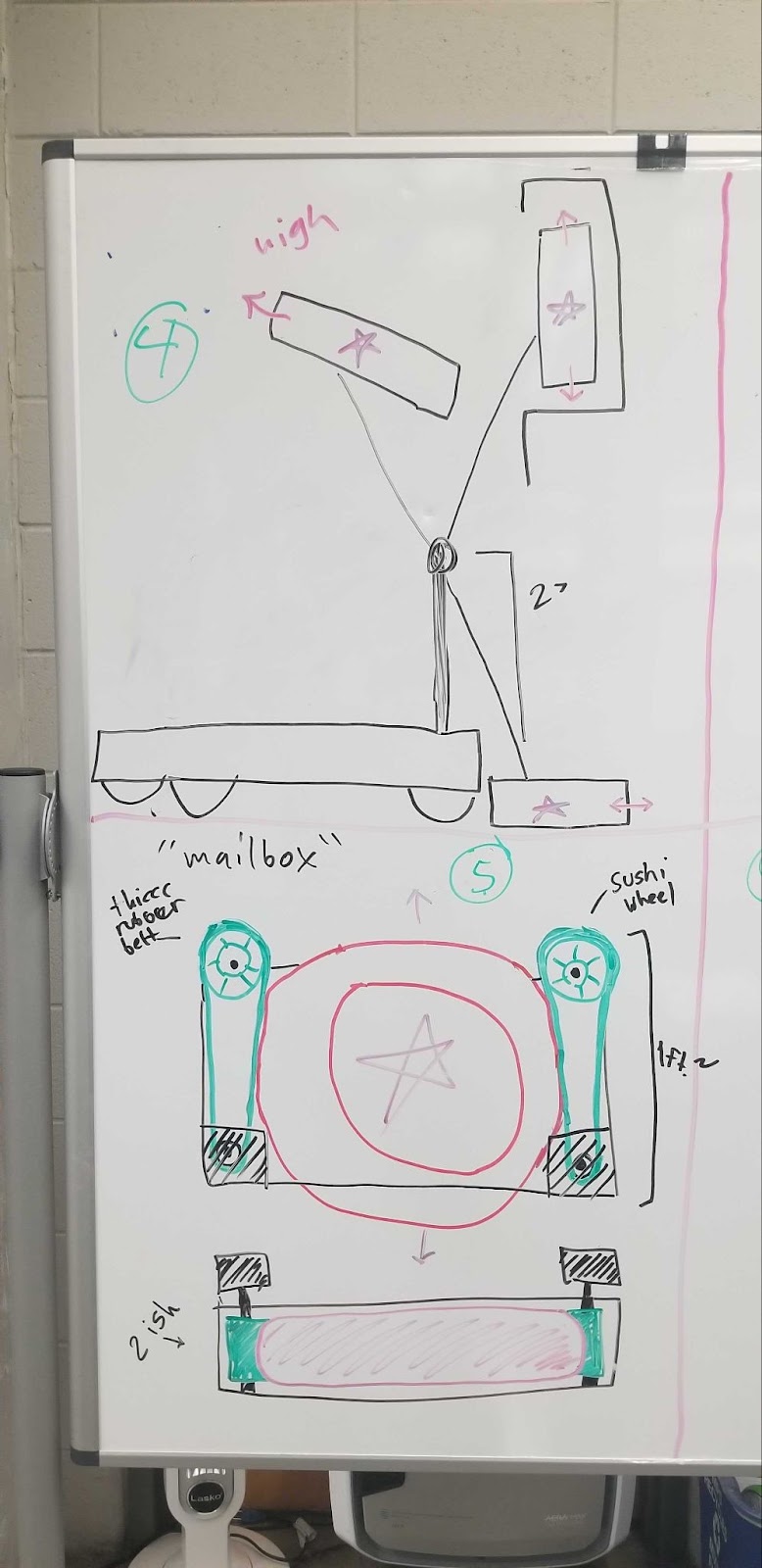
Initial Geometry Investigations

With these goals in mind, our designers have begun to look at some of the geometry and limitations that these might entail.

Intake arm with pass-through (we’ve been calling this the mailbox concept) for scoring in the amp:

Under-bumper intake with static angle shooter:

Over-bumper with pass-off to static shooter:

Conclusion

Overall, I think this was a very successful kickoff. We had a lot of great engagement and came up with a strategy that should be both effective and within our means to accomplish.

Next up: Prototyping and CAD v1

Until next time!

7 Likes

Great update as always Adam! Love the two robot concepts presented, looks like you guys are off to a very productive start

3 Likes

Prototypes

Over the past week, most of the team has been focused on pulling together several prototypes to validate some of the design concepts that were laid out during our initial game breakdown.

Note, that UPS has not had a lot of success in our history with wheeled shooters in general, so we’re pushing out boundaries a bit here. Overall, we don’t feel that the complexity of this task is beyond our capabilities, largely because we’re not having to deal with multiple game objects or spin (for the most part).

The last (only?) effective wheeled shooter the team built was in 2013. With another attempt (emphasis on attempt) in 2017. The only effective shooters we’ve build since then were either linear launchers or catapults.

The 4 prototypes that are being looked at:

  1. Side rollers - shooter
  2. Top roller with spatula - ground intake
  3. Top and bottom rollers - Shooter and ground intake
  4. Pusher - shooter

All of the pictures and videos we’ve taken of our prototypes can be found here: Prototype Media

Side Rollers

Originally envisioned as a possible intake/shooter, this prototype has largely evolved to validate the effectiveness of this design as a shooter.

SideRoller_GIF

Overall, between our prototyping and seeing other implementations of this shooter across Ri3D and OA teams, this seems to be a viable option. We did find that the compliant wheels are likely not the best option for a shooter, so we’ll continue to experiment on that front over the coming weeks.

Top Roller w/ Spatula

Inspired by our reworked gear intake design in 2017, which was heavily inspired by our friends at 1732, we felt a similar concept would work very well with this game object as well.

TopRoller_Spatula_GIF1 TopRoller_Spatula_GIF2

This idea works alright, but had some inconsistency that we did not see in some of our other concepts. We found that the requirement to “scrape” the ground as in 2017 was not as necessary with the notes, and also found the not material bound a little on the polycarb when compressed with the intake.

Top-Bottom Roller

We’re fairly confident that this will work well as an intake similar to 2011 and 2007, but wanted to check both materials as well as whether a top-bottom style shooter would also be effective with this game piece, as this could provide a significant benefit toward packaging the mechanisms together.

TopBottom_GIF

From our testing, this seemed to be more consistent than the side-wheel shooter, but that could be due to other factors like feeding consistency or wheel selection.

Snow and Concept Feedback

The Wisconsin winter hit us across the broadside Friday, dumping between 10-14 inches of snow across the region and closing schools. This meant we lost our first full Saturday meeting of the year, which definitely will hurt our schedule on top of missing our Monday meeting this week for MLK Day.

In light of these events and hoping to push some design decisions forward we started to collect online feedback on our 3 primary options for the design concept. We created 1 pagers with the high level designs what what they would take to implement and let the team provide pros/cons to each design. This will help the design and CAD team align on our final design.

Robot Concepts Slide Deck

Undertaker Concept

Originally proposed during our kickoff meeting, and taking some additional inspiration from fellow OA team 95 The Grasshoppers with their under-bumper/outside chassis intake concept.

Pass-Off Concept

A common thought I’ve seen thrown around for handling the notes. Seems to be a good solution overall and relatively low risk and easily implemented.

Pass-Through/Mailbox/Quokka Arm

Taking the initially proposed “mailbox” concept from out kickoff discussion, and drawing inspiration from the Ri3D Unqualified (shouldn’t this be Un-Koala-fied?) Quokkas team, we feel that this design is a good marriage of many of the concepts that the team has discussed and opens some options for improvement over the season with variable shots.

We’ll be leaving feedback open to the team through Monday at which point we’ll pull the feedback together and align on a final decision.


Signing out for now, from the frozen north.

door-open

7 Likes

undertaker-wwe
I love this and will absolutely be stealing it to refer to under-the-bumper intakes

5 Likes

Absolutely. I love this terminology.

1 Like

Our First 2024 Student Post

As mentioned in our kickoff, one of our goals is to drive further student engagement in OA, we want to have 7+ students write posts for our OA thread.

While I may the one doing the posting, the post was entirely written by the student.

With that said, let me introduce Noah, who has been leading the prototyping of the mailbox concept prototype.


Side Roller Manipulator High-Fidelity Prototype Log:

Monday January 8, 2024

  • Sketched out initial ideas for this concept which would involve two sets of compliant wheels with some squishy rubber belts that the note game piece could pass through. We believed this design could function as both a shooter and intake. We wanted to design the prototype so that we could modify the width between the two sets of compliant wheels and switch out the size of wheels we were using.
    |405.8915887850467x835.5888459587185

Wednesday January 10, 2024

  • After deciding on what parts we needed for the prototype, we collected the parts and decided to try the prototype without a squishy belt as a buffer between the note and the compliant wheels because we couldn’t find one that was suitable in the shop. We ran out of time for construction but had a sufficient vision.

Thursday January 11, 2024

  • We attempted to assemble the side roller concept and found that a piece of polycarb wouldn’t be suitable as the base for the design as it was too flexible and changed the width of our intake/shooter. We mounted the setup on a pair of parallel 1x1 beams instead. We began testing for the design…

Angled view [~25°]:|549.7109039192874x268.1673003802281

Front view:
|624x303.5105218143906

Eagle eye view:
|464.0000000912092x619

Top Down [floor] view:
|623.9867216315535x1281

After our initial test, a mentor pointed out that having a piece of polycarb over the top of the area between the compliant wheels would help to stop the note from leaving upwards too early and losing speed. We also faced some issues with the belts maintaining tension and decided to implement a static piece above each to maintain their tension.


5 Likes

Two post Tuesday, apparently.

While being buffeted by sub-zero temperatures over the last few days, we’re hoping that we’ll be able to have our first team meeting since last Thursday tomorrow. (Fingers crossed – schools were closed again today for temperature).

Luckily, we’ve been having good conversations about our designs via Slack so progress has not completely halted…

Concept Feedback

Here is a summary of feedback collected over the 3 proposed designs over the past few days.

Undertaker

Positives:

  • Can easily transit under stage
  • Safe intake, no deployment required
  • Fewer moving parts
  • Within our controls capability
  • Meets all scoring requirements

Concerns:

  • Possible high COG concerns to provide clearance under chassis
  • Limits space for electronics due to through-chassis note path
  • Integration between mechanism and chassis could cause delays. Hard to start wiring/programming until the entire mechanism is complete.
  • Picking (or manufacturing to) the wrong angle could leave us shooting from a poorly defined location.
  • Weight distribution may be strange

Pass-Off

Positives:

  • Always fits under stage
  • Most “UPS” of the 3 concepts
  • Within our controls capability
  • Meets all scoring requirements

Concerns:

  • Possibly requires additions of a pneumatic system (arm/deflector)
  • Could end up with a game piece stuck in chassis with no easy means to remove
  • Might limit footprint to add climber
  • Picking (or manufacturing to) the wrong angle could leave us shooting from a poorly defined location.

Pass-Through/Mailbox/Quokka Arm

Positives:

  • No pneumatic requirement
  • Most reliable amp scoring of the 3 options
  • Allows growth in adding additional shooting positions
  • Entire manipulator could be removed for maintenance
  • Meets all scoring objectives.
  • Possible upgrade to score in trap endgame?

Concerns:

  • All-in-one manipulator causes single point of failure for all game objectives.
  • More controls required than Undertaker or Pass-Off
  • Need to deploy intake to drive under stage.
  • High center of gravity concerns with intake up
  • Holding intake in starting position may require brake or kickstand
  • Needing to extend outside frame perimeter to score can be limiting under defense (lessons learned from our 2022 bot).

A Wild Fourth Concept Appears

In discussing the 3 proposed concepts, another concept was suggested that combined the ideas of several of the concepts proposed to limit the concerns outlined while accentuating the positive aspects of the design.

Under-Quokka

A combination of an under-bumper intake with a pass-off to a Quokka-style arm. Entire system stays within frame perimeter other than when scoring in amp.

Positives:

  • Good amp scoring
  • Drives under stage in starting configuration
  • Intake and shooter all within frame perimeter
  • Ability to iterated and add additional scoring positions
  • Within our controls capability

Concerns

  • Too complex for outlined team goals
  • May be difficult to see intake under bumper (would be same w/ undertaker)
  • Weight distribution may be weird.
  • Note path may be harsher than other designs
  • Smaller room for electronics than pass-through or pure-quokka.

We should have design alignment after our meeting tomorrow (assuming we can meet). After that we’ll be looking to have chassis CAD completed and released for manufacturing prior to our Saturday meeting.

Until next time!

2 Likes

Design Alignment

We have a decision! The team came together last night to have a final discussion and go through a design matrix comparing the robot concepts that were laid out (see previous post for details about the 4 design concepts. Thanks to fellow OA team 4481 - The Rembrandts for inspiration for the decision matrix which we made modifications to in order to align with our teams goals.

We had a conversation about how to weight each of the attributes relative to our goals as a team. Then we handed out decision matrix spreadsheets to the entire team and went through the concepts and implementations suggested for the 4 different concepts and then let the team fill out the matrix, took and took averages.


Design Alignment Document

After tallying the votes and doing some quick excel calculations the verdict came in and the concept we will be moving forward with is:

The Under-Quokka

Overall, the team felt this concept would meet all our goals, while being able to easily expand and improve our capability throughout the season. In addition, working entirely within our frame perimeter gives us more confidence that we can build a robust a reliable bot that will be an asset to alliances and minimize mechanical breakdowns and penalties.

Special shoutout to OA team, 95 - The Grasshoppers and Ri3D Team Unqualified Quokkas for inspiring this design. The amount of public resources available to learn and grow from over the past few years has been truly incredible, and we happy that we can support that effort in our own small way.

CAD

With the concept aligned upon, the CAD team has been unleashed to lock in designs for manufacturing. As mentioned before in our build thread, unfortunately our plasma cutter is out of commission for this build season so we’re needing to utilize precut gussets and limit our custom gussets to a lower number that we have in past years.

This adds a bit of challenge to our design process, but we will continue to charge forward.

Chassis CAD will be done and drawings made for manufacture prior to Saturday so we can begin construction.

Overall our goal is to have complete v1 CAD complete by the end of Saturday next week.

7 Likes

Noah’s Prototype Log, Pt2

We return to Noah for the conclusions of prototyping for the side-roller concept.

[insert several unexpected snow days]

Wednesday, January 17, 2024

  • Due largely to my team’s mechanical inexperience and the rushed nature of the first iteration of this prototype, there were severe enough problems encountered when we came back to test on Wednesday that it was decided the design should be heavily revamped so that testing could resume with the help of a more experienced member of the team. The most major problem was the compliant wheels rubbing on the aluminum frame due to warped metal and design inconsistencies (stacked washers…)

Thursday, January 18, 2024

  • With a few more hands, we decided on a modified version of the first prototype that could use its working half (one adjustable set of wheels). The other half of the prototype used a 3D printed part (linked and shown below) mounted on a 1x1 piece of aluminum. We sadly did not have enough of the 3d printed parts ready to use for both sets of wheels. It took us the entire meeting to construct the new prototype but the practice shots that we fired off brought hope to us. We designed a testing plan for Saturday morning (our final time allocated for prototyping).

6comp-9sep.mp4
4comp-9sep.mp4
5comp-5sep.mp4
6comp-5sep.mp4

Saturday, January 20, 2024

  • Results from our tests were that having wheels spaced 5in apart instead of 9in resulted in a similar distance. Maintaining near constant contact with the note rather than having a large gap is the best idea. I believe an array of wheels would work best rather than a belt because of the maintenance implications for a belt. All compressions performed similarly although our farthest shot used 4 inches.

  • Summary of what to do if this design is used for the actual robot:

    • Don’t use the stalk configuration as it does not maintain tension in the belts well and cause slight wobbling.
    • Use 6+ wheels or spaced out wheels with a belt for constant contact with the note and increased acceleration.
    • Between 4-6 inches should perform similarly for compression.

Intake image:

Top-down view:

|624x467.9685187286679

[END-TRANSMISSION]

3 Likes

First Post Kickoff Saturday

Having been snowed out last week, this was our first Saturday of build season in our actual build space (we host kickoff in another location for extra time). We had a highly productive meeting this week, with many teams making a lot of progress.

Subsystem Outlines and Naming

In previous seasons there has been some miscommunications occurring between the programming team and mechanical team (primarily) due to different naming conventions. This is largely due to the way these teams interact with the robot (we’re controlling the shoulder, not the arm), but occasionally caused issues when troubleshooting when we needed to set the “arm” angle, but that was not the variable carried through in the code. This was an easy fix, but should make high stress situations in the pit that much easier to work through when the whole team is speaking the same language.

At the same time we outlined the controls needs for each of the subsystems as they are currently envisioned. Some of the unknowns will be answered as the design is solidified, but for now we have a good enough understanding to move forward with no major concerns. The document that we’re tracking these requirements in can be found here: Design Updates

We have a good understanding of what we’ll be using for most of the needed sensors for each subsystem. The one major outstanding question is what we’ll be using as a sensor for indexing, we’ve done a bit of research in this area, but are very open to suggestions if people have had success with certain sensors in the past.

Design and Manufacturing

With the final alignment on our path forward, we now need a plan of what we need to take concept to reality. We have high confidence that this build is within our power, but we do have some obstacles to overcome and with an increased focus on control this year, there is a little additional design work to properly integrate sensors rather than “figure it out later”.

Over the past few days, the CAD team has made rapid progress on getting design work done such that construction can begin.

Chassis

  • 27x27 Swerve Base
  • 27x32 Total Frame Perimeter
  • SDS Mk4 Modules (L3 Gearing)

Chassis design was completed on time and prints of parts were delivered to the manufacturing team. All parts for chassis were cut (save the bellypan – material eta Monday). We should be able to begin assembly on Monday as well.

In additional all swerve modules were removed from last years chassis, disassembled, cleaned, greased, and reassembled within the course of the meeting. Great job to the team that handled that.

Undertaker

  • 2 Belt Driven Polycarb Rollers w/ Silicone Tubing and ThrifyBot roller plugs
  • 1 Unpowered PVC roller over 1/2" hex to help direct note over chassis rail
  • 2x Neo Motors, Direct Drive
  • 6 Bolts to remove subassembly for maintenance (or replacement)

The undertaker is nearing design completion, biggest open design question is shape and size of side wedges that will help redirect notes and protect the motors.

Arm

  • 2x 25:1 West Coast Products Arm Gearboxes, power by NEOs
  • Additional 4:1 external reduction for a total of 100:1 reduction
  • Dead axle using Rev Robotics MAXSpline shaft
  • Full range of motion (home to amp position) in ~0.5s
  • Rev Robotics through-bore encoder for position control
  • Limit switches and hard stop to define home position
  • Home position will be subwoofer shot as a default.

Arm design is nearly complete, a few details to work out regarding sprocket spacing and mounting our through bore encoder. We’re also planning to 3D print a MAXSpline to male hex adapter to interface with the through-bore encoder.

Full Robot CAD as of Jan 21

We made a lot of progress this week, and should still be on track to have full v1 CAD complete by next Saturday.

Field Elements

In additional to all of the other successes from this past Saturday, with our first access to our build space this year we were able to begin building field elements. The small team working on the field elements was incredibly productive, finishing the amp and most of the speaker in a single meeting. With the rate of work being done, we unfortunately failed to document the elements.

Conclusion

Right now everything has been going pretty smoothly. We’ve implemented a lot of new systems this year that have made everything from design decisions to order tracking much more organized. In a future post, I plan to document some of these systems, because they have made a massive difference in how the team has approached this season.

Until next time!

7 Likes

Open Alliance Programmer Update 1 - 1/21/2024

Hello, my name is Jake and I am the lead programmer on FRC 1675. I will be sharing some of what programming has been working on for the past few days. Firstly (and most importantly), we had a full subteam discussion about how we plan on breaking down our codebase this year right after deciding on a design.

We determined that there should be three main subsystems (excluding drive):

  1. Shooter
  2. Arm
  3. Undertaker

We determined the baseline requirements for these three subsystems (frc1675-2024-general/design/V1/requirements.md at main · frc1675/frc1675-2024-general · GitHub) and rewrote these ideas in terms of code using a class diagram:

(frc1675-2024-general/design/V1/class-diagram.md at main · frc1675/frc1675-2024-general · GitHub)

These requirements are designed to guide our “V1” robot code writing. The programming team, along with input from design and electrical, determined that these requirements outline the minimum functionality that we need to achieve before the first competition. While there are many ambitious ideas flying around the shop, we are taking a more systematic approach to ensure that our effort is correctly prioritized.

Aside from the discussions we had Saturday, we have been working on lots of research regarding sensory input and code quality. Several rookie programmers are working closely with electrical to produce a proof of concept for LaserCAN devices. We are hoping to use these rangefinders in our V1 iteration to detect pieces in our manipulators.

Meanwhile, the veteran programmers (including myself) have been working with more code quality assurance tools. I produced some code samples for unit testing, which we are hoping to integrate in to the robot program later in the season (due to the number of rookies). Code sample here. We also wrote some code in the build file to collect some information from git about the current state of the repository at compile time, which we can then store and display on the shuffleboard.

The idea here is that we are able to quickly tell what the state of the code was when it was deployed, which allows us to catch deploy mistakes and more quickly evaluate the robot before we go off to the field or begin debugging.

I am very excited about the steps we are taking to ensure code quality this year. Already, I have created more documentation than I have in all of my previous seasons. As well, the code we are implementing to control quality and help debugging presents exciting, fresh challenges which the veteran students are enjoying working through. I believe that these projects will take our code to the next level this year, and I am excited to be a part of that effort.

As far as the immediate future, I will work on verifying the base functionality of the swerve code this week, while rookies begin working on the base subsystem functionality and Michael (the other returning student) continues to work on more code quality projects, including logging. Looking forward to seeing what we will accomplish this season!

Documentation Repo

Robot Code Repo

2 Likes

Documentation and Logistics

Let’s talk about organization. I know we’ve all been there, we’re in the heat of build season and as usual, the first thing to slip is documentation and organization. As they say, a plan rarely survives first contact with the enemy. In past seasons, I’ve spent large portions of our very limited meeting time trying to track down parts required for assembly. This has directly impacted our expected delivery of both assemblies and completed robots.

This season, one of our goals was as a team was to improve both our organization and documentation with the intent of wasting less time during meetings, and having a complete view of design decisions and requirements that were made throughout the season.

Order Tracking

I’m sure plenty of other teams do this, but we committed to really keeping up with this sheet this year to track all orders out, and more importantly, where in the shop the parts were stored once they arrived.

No more “it should be in one of the 6 McMaster boxes”. Seems to be working well for us so far, and makes tracking the parts we have and need much easier.

Fabrication Tracking

For both internal fabrication, we create simplified PDF layout drawing of the specific processes that need to be done (cutting, drilling, etc). We then track progress through the fabrication process.

We’re also tracking all parts sent out for external fabrication, with our CNC plasma cutter unavailable this year, we’re leaning on Fabworks for some custom aluminum parts. #notsponsored.

Subsystem Outlines

In addition to keeping better track of all of our parts, we’ve spent some effort creating and keeping up with subsystem definition documents. These documents have 2 major purposes.

  1. Define the requirements and expectations of the subsystems for each of the sub-teams. This document can then be referenced for answers to basic questions without the need to constantly bounce between groups.
  2. Act as design documents that can be used as cheat sheets for preparing our pit crew to talk about how the subsystems were designed.

Example:

Links to subsystem definition documents:
(6.1) Subsystem Definition - Undertaker
(6.2) Subsystem Definition - Arm
(6.3) Subsystem Definition - Shooter

This is the first year we’ve implemented this type of documentation, but its made communication between the subteams much easier when the design decisions are documented in this fashion.

Conclusions

As a team that has struggled with organization due to (real or perceived) time constraints, we often in the past eschewed this level of documentation and logistics as unnecessary and additional overhead which we didn’t have time for.

Having gone through half a build season with these simple changes in place, it’s worth the time investment. Not only does investing a little time (which can be done away from the shop) save time in the long run, it also allows some of the mental burden keeping track of what needs ordered and where its located to be unloaded.

Just stay with it.

You Can Do It Exercise GIF by BoJack Horseman

Robot updates to follow soon.

5 Likes

CAD Updates

We have completed V1 CAD!

Onshape: 1675_24_ROBOT

We held an initial design review Saturday afternoon during our meeting, updates were made on Sunday by our designers and parts were released for fabrication Sunday night. We are hoping to have all parts in by next week to begin assembly.

Undertaker

(6.1) Subsystem Definition - Undertaker

Under-the-bumper, outside the drive base design. 2 Powered rollers, one passive roller. Angled deflectors with geometry to be experimented with as we go.

Inspired by
95 - The Grasshoppers (Undertaker concept)
2713 - Red Hawk Robotics (Modular Design)
3847 - Spectrum (Partially covered rollers and diverters)

Arm

(6.2) Subsystem Definition - Arm

Earlier this week, our student designer Will put together this writeup about the arm design:

The 1675 Design team recently finalized the design for our arm subassembly. This year our arm will be used to move our main manipulator to different scoring positions to allow amp and speaker scoring from different locations on the field. The arm assembly is composed of 2 main parts: the arm, and the A-frame. The A-frame is the structural component supporting the arm and it is made mainly out of grid-patterned MAXTube and custom manufactured 6061 aluminum gussets. The frame is attached to the chassis and belly pan by a pair of MAXtube rails that run the length of the chassis. The arm itself rests between the supports on a MAXspline shaft axle. The arm will be raised and lowered using 2 Neos connected to the arm tubes through a gearbox and chain with a total reduction of 100 to 1. The design team’s goal is to finish Revision A CAD by the end of this week, and completing the arm assembly was a huge leap forward.

Inspired by: Nature(?) – its an arm… do we need further inspiration?

Shooter

(6.3) Subsystem Definition - Shooter

Top-bottom wheeled shooter shooter design. Feeder section compliant wheels feeding 3in shooter wheels geared for 2:1 speed increase.

Inspired by:
Ri3D - Unqualified Quokkas (Basic concept)
111 - Wildstang (Side compression to increase contact area)

Prototyping Updates

While the CAD team was finishing up the design in the virtual world, prototyping teams were hard at work developing high-fidelity version of the undertaker and shooter based on the CAD designs/dimensions.

Undertaker

The undertaker prototype proved the concept works largely as expected. We found that too much compression from the front roller into the carpet caused occasional stall conditions, so that compression was reduced from 0.5in → 0.375 inches, with the goal of that front roller being largely to throw the note into the back roller to get sucked into the intake.

Undertaker

Undertaker2

Shooter

The shooter prototype found that sharp edges around when the note is being drawn into the shooter causes a “zesting” problem. They then found a simple solution to round of those edges with some deflectors. Similar deflectors will be added to the final design to prevent and extra zesty shooter.

Shooter1

Full System

The undertaker and the shooter were then combined to validate the concept of the entire system. Overall, this was a pretty successful initial system integration given the improvised nature of the setup. We expect significantly more speed out of the shooter when not being powered by drills.

FullSystem1

Videos of all the high fidelity prototypes can be found here: High Fidelity Prototypes

Overall, things are looking pretty good right now. We’re doing alright on schedule and progress is continuing at a good pace. Now we move into fabrication and assembly.

7 Likes

Slow Week

Going to be a bit of a shorter update this week (he says optimistically). We sent our parts to be manufactured last week, and they should be arriving on Tuesday (fingers crossed).

With that in mind, we spent the majority of the week preparing for when our CNC parts arrive to quickly assemble and get our robot functional.

Stuff we’ve done this week:

  • Pre-cut all extrusion needed for arm and shooter assemblies to length
  • Cut and install undertaker rollers with silicone tubing. (As laid out this was indeed easier with the application of some isopropyl alcohol – which was recommended as the intended route right away)
  • Migrate swerve modules from last years chassis to this year’s chassis.
  • Prewire chassis for drive and arm controls
  • Lay out field dimensions for testing
  • Design a pile of parts for sensors that would usually be “we’ll figure it out later” stuff
  • Confirm all of the bolts and fasteners needed for assembly and order from McMaster.
  • Finish first drafts of award submissions

(And more that I’m likely missing or forgetting)

The Detail Work

The world might be ending – properly designed sensor mounts:

Arm hardstop/limit switch (Rev magnetic limit switch)

Rev through-bore encoder with Rev spline to hex 3D printed interface:

LaserCAN for indexing:

Anti-zest deflectors on shooter intake:

And most impressively (for 1675) an RSL mount designed intentionally, in the CAD, and not just something we slapped together in the pit last second.

Go time

This week we have an aggressive, but achievable set of goals, the result of which should be a mostly functional robot by the end of the day next Saturday.

Goals for this week:

Monday

  • Mechanical - cut and tap hex shaft for all sub-assemblies (cut to 1/2in extra length so they can be trimmed to final dimensions upon sub-assembly)
  • Electrical - complete drive wiring and wire Undertaker motor controllers

Wednesday

  • Submit final draft of Woodie Flowers Award nomination to FIRST
  • Mechanical - attach Chassis side sheet metal plates and build Undertaker assembly/attach to drive base
  • Electrical - wire Undertaker motors to drive base

Thursday

  • Programming/Electrical - Chassis and Undertaker debug
  • Mechanical - build Arm sub-assembly

Saturday Morning

  • Mechanical - Attach Arm to drive base and build shooter sub-assembly
  • Electrical - wire Arm motors

Saturday Afternoon

  • Mechanical - Attach shooter sub-assembly to Arm
  • Electrical - Wire shooter sub-assembly motor controllers
  • 95% Mechanical and Electrical completion

Hope to be able to show all of this progress over the next few updates.

3 Likes

Time to build

CNC parts from Fabworks arrived this past Tuesday which allowed rapid progress to be made throughout the week. We had a minor issue with a couple of CNC parts not being in our initial delivery, but the team at Fabworks were able to overnight the missing parts which allowed us to not lose any time.

Since we don’t meet Tuesdays, the Wednesday, Thursday, and Saturday meetings were packed with things to do.

We weren’t able to quite make it through everything we had hoped to this week, but things are looking very promising. We should be driving and intaking early this week, and should have a full working robot by next Saturday. (Fingers crossed).

With that, I present a Super Bowl Sunday photo dump:

Chassis/Drivetrain assembly and wiring

Adding the undertaker mounting plates

Installing the battery box, and attacking the camera

Final chassis assembled

Undertaker assembly

Assembling the intake rollers

Assembling with an assist from CAD

Tap-tap-tap it in…

Test assembly

Test fit on the chassis

Final undertaker assembly, ready to be installed.

Arm Assembly

Making efficient use of the M12 Rivet Tool

Arm parts glamor shot

Always reference the CAD…

Test fit with the arm pivot

Cutting chain…

Shooter Assembly

Shooter parts, care of Fabworks

Installing hubs in shooter wheels

Partial assembly

Test fit full assembly

Mostly complete final assembly with weight

Programming

While the mechanical and electrical teams were hard at work assembling and wiring the robot, the programming team was heads down trying to prepare for initial integration checks when the robot is handed over.

For details, someone else will need to provide insight, but it seems like subsystems are in a place where we should be testing right away.

The programmers also took a first swing at a new process we’re trying this year in doing a DFEMA (Design failure mode effects and analysis) in an attempt to minimize the impact of failures through detection and preventive mitigation. This will be detailed after mechanical has a chance to perform this analysis as well.

First weigh-in

While not fully assembled, all expected parts were loaded on the scale for a first real-life check on weight… coming in at a slim 91.5 lbs. This is a nice weight at leaves us plenty of room to make changes, and possibly add a climber. (TBD)

Next Up

  • Final assembly and wiring
  • Initial systems integration and testing
  • A fully functional robot (hopefully)

We’re a little more than a month our from our first regional here in Milwaukee, so we’re hoping to have a good chance to get some solid driver practice in.

3 Likes

Two steps forward, one step back

We made a lot of forward progress last night, though it doesn’t look like much work was done as we spent much of the meeting finalizing the assemblies for the undertaker, arm, and shooter.

We were able to do our first power on check. Nothing exploded so we’re considering that a massive success. A+ job by our electrical crew.

We also spent some time adding the magnetic limit switches to the arm and improving the arm support and spacers. This should be ready to install on Wednesday.

Shooter was disassembled, shafts cut to exact lengths and then (mostly reassembled). Wheels and spacers need to be finalized, but looking good for a Wednesday install.

Arm mount was reinstalled on the chassis.

Finally, the undertaker was rebuilt with v2 of the diverters and should be ready for testing soon™.

Making slow but steady progress. Things are still looking on track to have full designed robot functionality up and running on Saturday.

3 Likes

It looks like a robot

Short update today, robot is about 95% complete mechanically and about 75% complete electrically. Our electrical team should have unfettered access to the robot tonight to allow programmers full access Saturday for systems testing.

We’re slightly behind our ideal schedule, but miles ahead of both where we were last year as well as where we’ve been in most previous years.

And a quick manual check of our note path:
ezgif.com-video-to-gif-converter

Next Up

  • Systems integration
  • Naming
2 Likes